14.8 Rover MEMS - MPi/SPi
Turbocharger
Referto Chapter 2 fora detailed description
of turbocharger operation. An intercooler,
which is a kind of air radiator, for cooling is
used in Rover turbo models. Boost control is
controlled by the ECMso that maximum use
is made of the turbo during appropriate
operating conditions.
Air by-pass (turbo models)
Turbo lag is reduced on Rover turbo
models by use of an air by-pass valve. A
sensing pipe connects the by-pass valvewith
the inlet manifold. When the turbine supplies
compressed air to the manifold, the
compressed air pushes upon the air by-pass
valve,and it remains shut. Duringdeceleration
or light load when the turbo is inactive, the
manifold contains depressed air (a vacuum)
and the depression willopen the air by-pass
valve. Airpressure from the impellerwheel is
circulated throughout the turbocharger
housing, and prevents a back pressure
forming. The turbine slows very little, and
turbo lag is much reduced when the
accelerator is re-applied.
6 Catalyticconverter and
emission control
'
1
1
I.
I
From January 1993, all new cars in the UK
are fitted with a catalyst as standard
equipment.
Adjustments
~
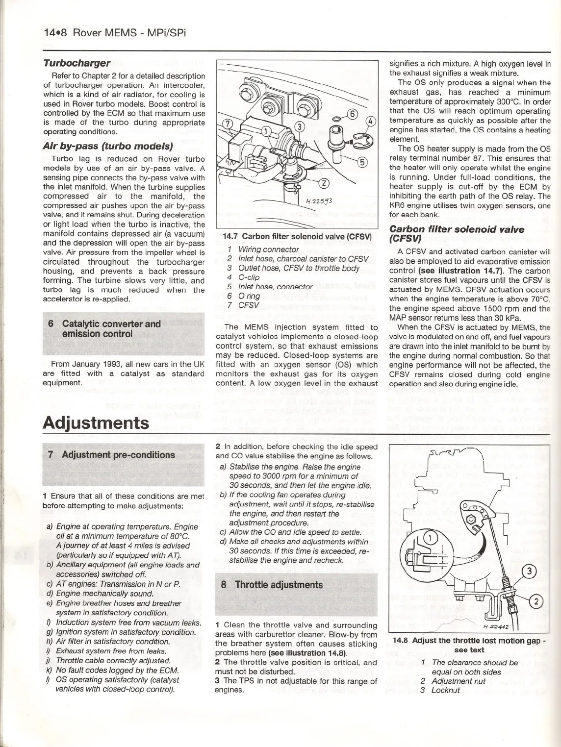
14.7 Carbon filter solenoid valve (CFSV)
1 Wiringconnector
2 Inlethose, charcoalcanister to GFSV
3 Outlethose, GFSVto throttlebody
4 G-cIip
5 Inlethose, connector
6 0 ring
7 GFSV
The MEMS injection system fitted to
catalyst vehicles implements a closed-loop
control system, so that exhaust emissions
may be reduced. Closed-loop systems are
fitted with an oxygen sensor (OS) which
monitors the exhaust gas for its oxygen
content. A low oxygen level in the exhaust
signifiesa rich mixture.A high oxygen levelin
the exhaust signifiesa weak mixture.
The OS only produces a signal when the
exhaust gas, has reached a minimum
temperature of approximately300°C. In order
that the OS will reach optimum operating
temperature as quickly as possible after the
engine has started, the OS contains a heating
element.
The OS heater supply is made from the OS
relay terminal number 87. This ensures that
the heater willonly operate whilst the engine
is running. Under full-load conditions, the
heater supply is cut-off by the ECM by
inhibitingthe earth path of the OS relay. The
KR6engine utilises twin oxygen sensors, one
for each bank.
Carbon filter solenoid valve
(CFSV)
A CFSVand activated carbon canister will
also be employed to aid evaporative emission
control (see illustration 14.7). The carbon
canister stores fuel vapours until the CFSVis
actuated by MEMS.CFSV actuation occurs
when the engine temperature is above 70°C,
the engine speed above 1500 rpm and the
MAPsensor returns less than 30 kPa.
When the CFSV is actuated by MEMS,the
valveis modulated on and off,and fuelvapours
are drawn into the inletmanifoldto be bumt by
the engine during normalcombustion. So that
engine performance willnot be affected, the
CFSV remains closed during cold engine
operation and also duringengine idle.
~
'I
I
~
7 Adjustmentpre-conditions
1 Ensure that all of these conditions are met
before attempting to make adjustments:
I
a) Engine at operating temperature. Engine
oilat a minimumtemperatureof aOOG.
Ajourney of at least 4 miles is advised
(particularly so if equipped with A1).
b) Ancillary equipment (allengine loads and
accessories) switched off.
c) AT engines: Transmission in N or P.
d) Engine mechanically sound.
e) Engine breather hoses and breather
system in satisfactory condition.
f) Induction system free from vacuum leaks.
g) Ignition system in satisfactory condition.
h) Air filter in satisfactory condition.
ij Exhaust system free from leaks.
j) Throttle cable correctly adjusted.
k) No fault codes logged by the EGM.
I) OS operating satisfactorily (catalyst
vehicles with closed-loop control).
.1
I
l
2 In addition, before checking the idle speed
and CO valuestabilise the engine as follows.
a) Stabilise the engine. Raise the engine
speed to 3000 rpm fora minimum of
30 seconds, and then let the engine idle.
b) Ifthe cooling fan operates during
adjustment, wait untilit stops, re-stabilise
the engine, and then restart the
adjustment procedure.
c) Allowthe GOand idlespeed to settle.
d) Make allchecks and adjustments within
30 seconds. If this time is exceeded, re-
stabilisethe engine and recheck.
8 Throttleadjustments
1 Clean the throttle valve and surrounding
areas with carburettor cleaner. Blow-byfrom
the breather system often causes sticking
problems here (see illustration 14.8).
2 The throttle valve position is critical, and
must not be disturbed.
3 The TPS in not adjustable for this range of
engines.
JSC~-'I
14.8 Adjust the throttle lost motion gap -
see text
1 The clearanceshould be
equal on both sides
2 Adjustment nut
3 Locknut


