14-6 Rover MEMS - MPi/SPi
"
running, the stepper motor will open the
throttle so that the engine rpm willbe set to a
suitable fast idle speed. Also, on sensing low
battery voltage, the ECMwillincrease the idle
speed to allowgreater alternator output.
The stepper motor is a DC motor, provided
with a voltage supply from the system relay.
The motor windings are earthed through four
earth wires. Byearthing various combinations
ofthe four wires, the ECMis able to indexthe
motor to its correct position. The ECM
controls idle speed by using the stepper
motor in one of two diverse ways.
Throttle plate actuator
The stepper motor controls a cam and
pushrod through a reduction gear. The
pushrod contacts the throttle lever, which
actuates the throttle plate and so maintains
the correct idle speed. Maximummovement
of the stepper motor is 3.75 revolutions, and
this is accomplished by 180 steps of 7.5°.The
reduction gear reduces the actual cam
movement to 150°.
Inlet manifold air valve
The air valve stepper motor is an actuator
that the ECM uses to automatically control
idle speed during normal idle and during
engine warm-up. When the throttle is closed,
the throttlevalve is locked in a position where
very littleair passes by. The throttle position
then, willhave no effect upon the idlespeed.
A by-pass port to the throttle plate is
located in the inlet manifold. A valve is
positioned inthe port. As the valvemoves, the
volume of air passing through the port will
vary, and this directly affects the idle speed.
The idle speed then, depends upon the
positionofthe stepper air valveinthe by-pass
port. This method of idle control is fitted to
some models (principally those with the
plastic inletmanifold)fromthe middleof 1994.
Adaptive idle control
Since the idle control is adaptive, over a
period of time, the ECM will learn the best
position for a particular engine - irrespective
of age, engine condition and load, so that the
correct idle speed is always maintained.
Consequently, a replacement ECMwillneed
sometimeto re-learnthe systemparameters
beforeproper idlecontrol is restored.
Adaptive idle measurements are retained in
non-volatile memory and cannot be lost -
even if the vehicle battery is removed. On
models prior to 1993, idle position was
determinedby an idle switch locatedon the
acceleratorpedal.From1993, this switch has
been discontinued,and the idle positien is
now determined by the TPS.
.'
It
I
I,
I.'
11
.,
I:
I,
JI
I:
Manifold heater (SPi)
The ECM controls the manifold heater
through a relay. This heater works on the PTC
principle, and allows a greater current to
quickly heatthe inlet manifold during the warm-
up period. This allows better driveability during
engine warm-up. Once a preset temperature of
U
...!....
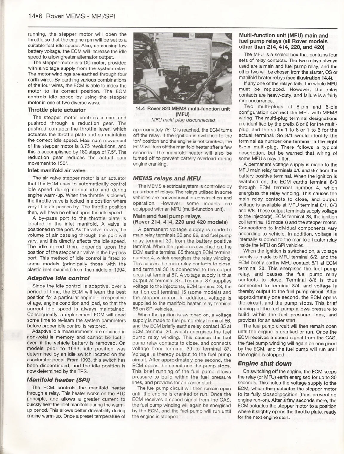
14.4 Rover 820 MEMS multi-function unit
(MFU)
MFU multi-plug disconnected
approximately 75° C is reached, the ECM tums
off the relay. If the ignition is switched to the
'on' position and the engine is not cranked, the
ECM will turn off the manifold heater after a few
seconds. The manifold heater will also be
turned off to prevent battery overload during
engine cranking.
MEMS relays and MFU
The MEMS electrical system is controlled by
a number of relays. The relays utilised in some
vehicles are conventional in construction and
operation. However, some models are
equipped with an MFU (multi-function unit).
Main and fuel pump relays
(Rover 214, 414, 220 and 420 models)
A permanent voltage supply is made to
main relay terminals 30 and 86, and fuel pump
relay terminal 30, from the battery positive
terminal. When the ignition is switched on, the
ECM earths terminal 85 through ECM terminal
number 4, which energises the relay winding.
This causes the main relay contacts to close,
and terminal 30 is connected to the output
circuit at terminal 87. A voltage supply is thus
output at terminal 87. Terminal 87 supplies
voltage to the injector(s), ECMterminal 28, the
ignition coil terminal 15 (some models) and
the stepper motor. In addition, voltage is
supplied to the manifold heater relay terminal
86 on SPi vehicles.
When the ignition is switched on, a voltage
supply is made to fuel pump relay terminal 86,
and the ECM briefly earths relay contact 85 at
ECM terminal 20, which energises the fuel
pump relay winding. This causes the fuel
pump relay contacts to close, and connects
voltage from terminal 30 to terminal 87.
Voltage is thereby output to the fuel pump
circuit. After approximately one second, the
ECM opens the circuit and the pump stops.
This brief running of the fuel pump allows
pressure .to build within the fuel pressure
lines, and provides for an easier start.
The fuel pump circuit will then remain open
until the engine is cranked or run. Once the
ECM receives a speed signal from the CAS,
the fuel
pump winding will again be energised
by the ECM, and the fuel pump will run until
the engine is stopped.
Multi-function unit (MFU)main and
fuel pump relays (all Rover models
other than 214, 414, 220, and 420)
The MFU is a sealed box that contains four
sets of relay contacts. The two relays always
used are a main and fuel pump relay, and the
other two will bechosen from the starter, OS or
manifold heaterrelays (see illustration 14.4).
If anyone of the relays fails, the whole MFU
must be replaced. However, the relay
contacts are heavy-duty, and failure is a fairly
rare occurrence.
Two multi-plugs of 8-pin and 6-pin
configuration connect the MFU with MEMS
wiring. The multi-plug terminal designations
are identified by the prefix 8 or 6 for the multi-
plug, and the suffix 1 to 8 or 1 to 6 for the
actual terminal. So 8/1 would identify the
terminal as number one terminal in the eight
8-pin multi-plug. There follows a typical
description, but be warned that wiring of
some MFU's may differ.
A permanent voltage supply is made to the
MFU main relayterminals 8/6 and 8/7 from the
battery positive terminal. When the ignition is
switched on, the ECM earths terminal 6/3
through ECM terminal number 4, which
energises the relay winding. This causes the
main relay contacts to close, and output
voltage is available at MFU terminal 8/1, 8/3
and 8/8. These output terminals supply voltage
to the injector(s),ECM terminal 28, the ignition
coil terminal 15 models)and the stepper motor.
Connections to individual components vary
according to vehicle. In addition, voltage is
intemally supplied to the manifold heater relay
insidethe MFU on SPi vehicles.
When the ignition is switched on, a voltage
supply is made to MFU terminal 6/2, and the
ECM briefly earths MFU contact 6/1 at ECM
terminal 20. This energises the fuel pump
relay, and causes the fuel pump relay
contacts to close. Terminal 8/6 is thus
connected to terminal 8/4, and voltage is
thereby output to the fuel pump circuit. After
approximately one second, the ECM opens
the circuit, and the pump stops. This brief
running of the fuel pump allows pressure to
build within the fuel pressure lines, and
provides for an easier start.
The fuel pump circuit will then remain open
until the engine is cranked or run. Once the
ECM receives a speed signal from the CAS,
the fuel pump winding will again be energised
by the ECM, and the fuel pump will run until
the engine is stopped.
Engine shut down
On switching off the engine, the ECM keeps
the relay (or MFU) earth energised for up to 30
seconds. This holds the voltage supply to the
ECM, which-thef-l actuates the stepper motor
to its fully closed' osition (thus preventing
engine run-on). After a seconds more, the
ECM actuates the stepper motor to a position
where it slightly opens the throttle plate, ready
for the next engine start.


