14.10 Rover MEMS -MPi/SPi
EOH1417
8 9 33 30 16
e'arth
KS TPS CTS ATS
14.10 Typical local wiring diagram:
sensors
2 Voltage to the injectors is provided from
either.the system
relay or MFU.
3 The SPi system is current-controlled.
4 The injector resistance is normally 1.1 to
1.5 ohms.
16 Phase sensor (CID)
1 Referto the notes at the start of Section 11,
and refer to the relevant Section of Chapter 4.
2 The CID phase sensor is located adjacent
to the camshaft.
3 Unfortunately, no data is available for CID
resistance, but failure is likely to be indicated
bya short- or open-circuit reading.
17 MAP sensor
1 Refer to the notes at the start of Section 11,
and refer to the relevant Section of Chapter 4
(see illustration 14.10).
2 The MAP sensor is incorporated.
into the
ECM, and separate voltage tests are not
possible.
3 Performance of the MAP sensor can be
quickly evaluated by a suitable FCR attached
to the serial port. Select Datastream; the
values should be similar to those detailed in
the MAP table (see Chapter 4, Section 18).
18 Airtemp,eraturesensor (ATS)
1 Refer to the notes at the start of Section 11,
and refer to the relevant Section of Chapter 4.
2 The ATS is mounted in the air inlet casing
(MPi) or in the air filter casing (SPi).
--~-"""'~ ~ .-
19 CGolant temperatUre sensor
(CTS)
--'-"""""''''
1 Refer to the notes at the start of Section 11,
and refer to the relevant Section of Chapter 4.
I
Jo>:
20 Throttle switch (TS)
1 On pre-1993 models equipped with the
throttle pedal.-mounted 'idle switch', the
engine will gasp, die and fail to respond
properly if the engine speed is increased by
moving the throttle lever directly from under
the bonnet. This is because the ECM links the
idle switch closed condition with rpm, and
enters fuel deceleration cut-off mode. The
engine rpm should only be increased by use
of the accelerator pedal from inside the car.
2 However, during testing it is sometimes
more convenient to be able to control the
engine speed by moving the throttle lever
directly. It is possible' to by-pass the idle
switch by disconnecting one 'of the wires on
the pedal switch. MEMS will assume a fault,
and set a default value. The engine will then
respond to throttle lever movement. .
3 Once testing is complete, the pedal switch
wire must be reconnected, and a FCR used to
clear the ECMof any
logged faults.
4 Check that the terminal pins are pushed
home and making good contact with the
pedal switch.
Checking pedal switch operation
5 The two wires to the pedal switch multi-
plug connector are earth and idle signal.
6 With the engine stopped, and ignition on,
connect the voltmeter negative probe to an
engine earth.
7 Connect the voltmeter positive probe to the
wire
attached to the pedal switch signal
terminal number 2.,The meter should indicate
zero volts.
8 If zero volts cannot be obtained:
a) Check the pedal switch earth connection.
b) Make the pedal switch resistance tests
(below).
9 Crack open the throttle. The voltage should
rise to 5.0 volts.
10 If the voltage is low or non-existent:
a) Check that the pedal switch idle terminal
is not shorted to earth.
.
b) Disconnect the pedal switch connections,
and check for5.0 volts at the signal
terminal.If there is no voltage, check for
continuityof the signal wiringbetween the
pedal switch
and the ECM.
11 If the pedal switch wiring is satisfactory,
check all voltage supplies and earth
connections to the ECM. If the voltage
supplies and earth connections are
satisfactory, the ECM is suspect.
Pedal switch resistance tests
12 Connect an ohmmeter between the earth
terminal 1 and terminal 2.
13 With the pedal switch closed, the
ohmmeter should indicate very close to zero
ohms.
14 Slowly open the throttle, and as the pedal
switch cracks open, the resistance should
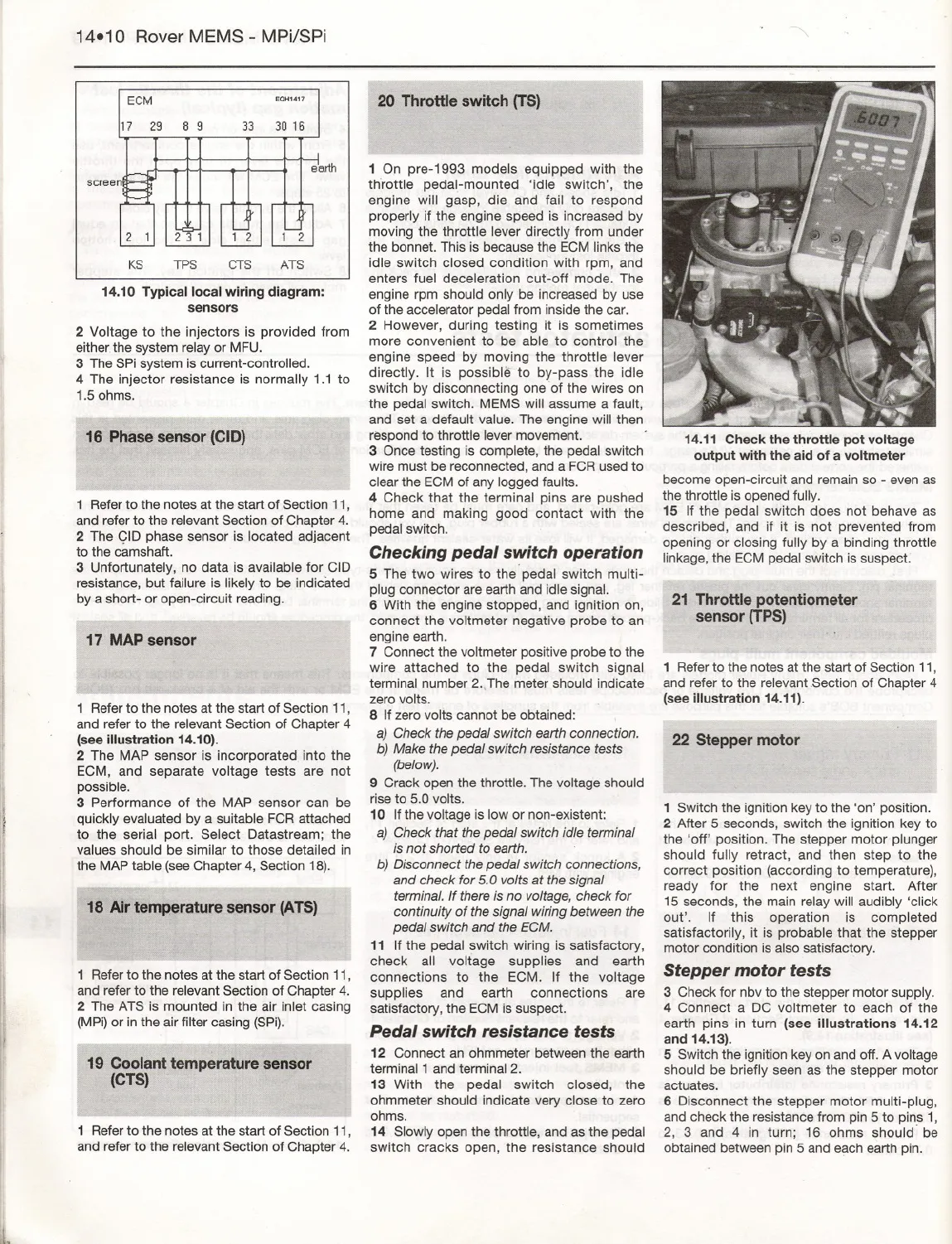
14.11 Check the throttle pot voltage
output with the aid of a voltmeter
become open-circuit and remain so - even as
the throttle is opened fully.
15 If the pedal switch does not behave as
described, and if it is not prevented from
opening or closing fully by a binding throttle
linkage, the ECM p.edalswitch is suspect.
21 Throttle potentiometer
sensor (TPS)
1 Refer to the notes at the start of SectiOn 11,
and refer to the relevant Section of Chapter 4
(see
illustration 14.11).
22 Stepper motor
1 Switch the ignition key to the 'on' position.
2 After 5 seconds, switch the ignition key to
the 'off' position. The stepper motor plunger
should fully retract, and then step to the
correct position (according to temperature),
ready for the next engine start. After
15 seconds, the main relay will audibly 'click
out' . If this operation is completed
satisfactorily, it is probable that the stepper
motor condition is also satisfactory.
Stepper motor tests
3 Check for nbv to the stepper motor supply.
4 Connect a DC voltmeter to each of the
earth pins in turn (see illustrations 14.12
and 14.13).
5 Switch the ignition key on and off. A voltage
should be briefly seen as the stepper motor
actuates.
6 Disconnect the stepper motor multi-plug,
and check the resistance from pin 5 to pins 1,
2, 3 and 4 in turn; 16 ohms should' be
obtained between pin 5 and e?ichearth pin.
Throttle Pedal Switch wire colours believed to be pink/grey and black/pink


