Rover MEMS - MPi/SPi 14.9
--- t-- - - - -----
9 700 timingchecks
.p... ----
1 The ignition timing is not adjustable on
these models, and timing marks are not
provided.
, - -- --
10 Idle adjustments
I
Adjustments (idle tune)
1 Idle speed and CO level (non-cat models
only) are only adjustable through the use of a
suitable FCR connected to the serial port.
2 Before connecting the FCR, check the
throttle lost motion gap.
3 After completing the idle tune, recheck the
throttle lost motion gap.
System sensor and actuator tests
Adjustment of the throttle lost
motion gap (typical)
4 Switch the ignition on.
5 From within the engine compartment, use
the throttle lever to fully open the throttle
valve. The ECM will index the stepper motor
to 25 steps.
6 Allow the throttle valve to fully close.
7 Adjust the throttle cable so that an equal
gap exists either side of the lost motion
lever.
8 Switch off the ignition key. The stepper
motor will revert to normal control.
Important notes
Please refer to Chapter 4, which describes common test procedures applicable to this system. The routines in Chapter 4 should be read in
conjunction with the component notes and wiring diagrams presented in this Chapter. The wiring diagrams and other data presented in this
Chapter are necessarily representative of the system depicted. Because of the variations in wiring and other data that often occurs, even between
similar vehicles in any particular VM's range, the reader should take great care in identification of ECM pins, and satisfy himself that he has
gathered the correct data before failing a particular component.
MEMSECMterminals
The multi-plug terminals at the MEMS ECM are gold-plated, and care must be taken that the plating is not removed during procedures that
involve probing or back-probing. The terminal wires are sealed with a rubber plug, and you should not back-probe through these plugs, or pierce
them with a sharp object. If the rubber plug is damaged, it will lose its water-sealant qualities. The following method is strongly recommended to
prevent damage to terminal or sealing plug.
First, disconnect the multi-plug and detach the white cover. Carefully insert a small jeweller's-type screwdriver into the recess at the top of the
terminal pin. Gently lever out the plastic retainer leg, and gently pull on the wire from behind the multi-plug. Once the clip is disengaged, the
terminal should slide easily from its holder. Slide the rubber plug up the wire, and then push the terminal back into the multi-plug. Repeat this
procedure for all terminal pins that will be back-probed during a test. After testing is completed, the procedure should be reversed, and all sealant
plugs refitted into their original position.
Moulded component multi-plugs
From about 1994, many Rover models are fitted with moulded multi-plugs to the components. This means that it is no longer possible to
backprobe the component. Live voltage or oscilloscope tests must therefore be made at the ECM or with the aid of a break-out box (BOB).
Component BOB's suitable for this purpose are available from the suppliers of engine test equipment.
1 Refer to the notes at the start of this 1 Refer to the notes at the start of Section 11, 1 Referto the notes at the start of Section 11,
Section, and refer to the relevant Section of and refer to the relevant Section of Chapter 4. and refer to the relevant Section of Chapter 4.
Chapter 4. 2 A knock sensor is only used in 2.0 litre
2 The CAS resistance is 1100 to 1700 ohms engines with MPi.
11 Primarytrigger -
crank angle sensor (CAS)
12 Primary ignition
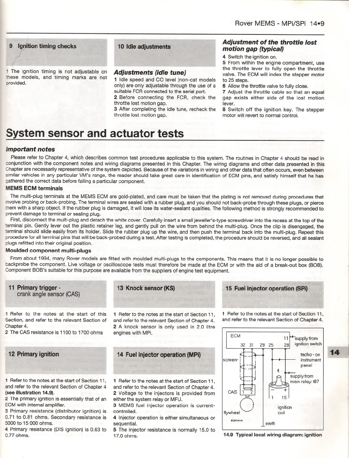
1 Referto the notes at the start of Section 11,
and refer to the relevant Section of Chapter 4
(see illustration 14.9).
2 The primary ignition is essentially that of an
ECM with internal amplifier.
3 Primary resistance (distributor ignition) is
0.71 to 0.81 ohms. Secondary resistance is
5000 to 15 000 ohms.
4 Primary resistance (DIS ignition) is 0.63 to
0.77 ohms.
13 Knock sensor (KS)
14 Fuel injector operation (MPi)
- - .J
1 Refer to the notes at the start of Section 11,
and refer to the relevant Section of Chapter 4.
2 Voltage to the injectors is provided from
either the system relay or MFU.
3 MEMS fuel injector operation is current-
controlled.
4 Injector operation is either simultaneous or
sequential.
5 The injector resistance is normally 15.0 to
17.0 ohms.
- - -.....
15 Fuel injectoroperation (SPi)
I
I
I
- - - lE
ECM
11
Isupplyfrom
281 ignition switch
tacho
-on
instrument
panel
CAS1' 2
fl>whOOIO
ignition
coil
EQH1414
earth
14.9
Typical local wiring diagram: ignition


