Rover MEMS - MPi/SPi 14-11
.ECM
2 3 22 27 24 23 . 26
suppty
frommain
relay: t87
23164
" Stepper
motor
EOH1418
inj 1 inj2 inj3 inj4
14.12 Typical local wiring diagram:
injectors, stepper motor
14.13 Stepper motor multi-plug
pin numbers
7 Disconnect the ECM multi-plug (refer to
Warning No 3 in Reference)
8 Switch the ignition key 'on'.
9 Connect a jumper lead from ECM pin 4 to
battery earth (this energises the main relay
with the ECM disconnected).
10 Connect
a voltmeter between earth and
ECM pins 22, 2. 27 and 3 in turn. nbv should
be obtained.
11 If nbv is not obtained at one or more of
the ECM pins. check the continuity of the
wiring between the relevant ECM and stepper
motor pins.
12 If the stepper motor wiring is satisfactory.
check all voltage supplies and earth
connection~ to the ECM. If -the' voltage
supplies and earth connections are
satisfactory, the ECM is suspect."
--- - - -- -- - -
23 i!Manifold heater
(SPi engines only)
-- . ---
----..--
1 Referto the notes at the start of Section 11.
and referto the relevant Section of Chapter 4.
2 Make tests when the engine coolant
temperature is less than 75°C. Note: If the
engine is hot. a variable potentiometer could
be connected to the CTS multi-plug so that a
cold engine could be simulated.
3 If a FCR is available. the manifold heater
relaycan be"actuated via the serial port. This
liould prove the integrity of the relay and
associated wiring.
14.14 Probing for nbv at the
ECMmulti-plug
- -.. - - -- - -.--
24 ECMvoltage supplies
and earths
1 Refer to the notes at the start of Section 11.
and refer to the relevant Section of Chapter 4
(see illustration 14.14). .
2 In addition to relay drivers for the main relay
and pump relay. relay drivers may be available
for the manifold heater and OS relays.
25 Inertia switch
1 Refer to the notes at the start of Section 11.
and refer to the relevant Section of Chapter 4.
2 Montego models only: check the ballast
resistor by-pass.
3 The inertia switch may be located behind
the radio (early models) or in the engine
compartment. close to the bulkhead.
ECM
29 36
18 72142028
EARTH
f
--.
screoen ~ ---
,..---
~ ::-H
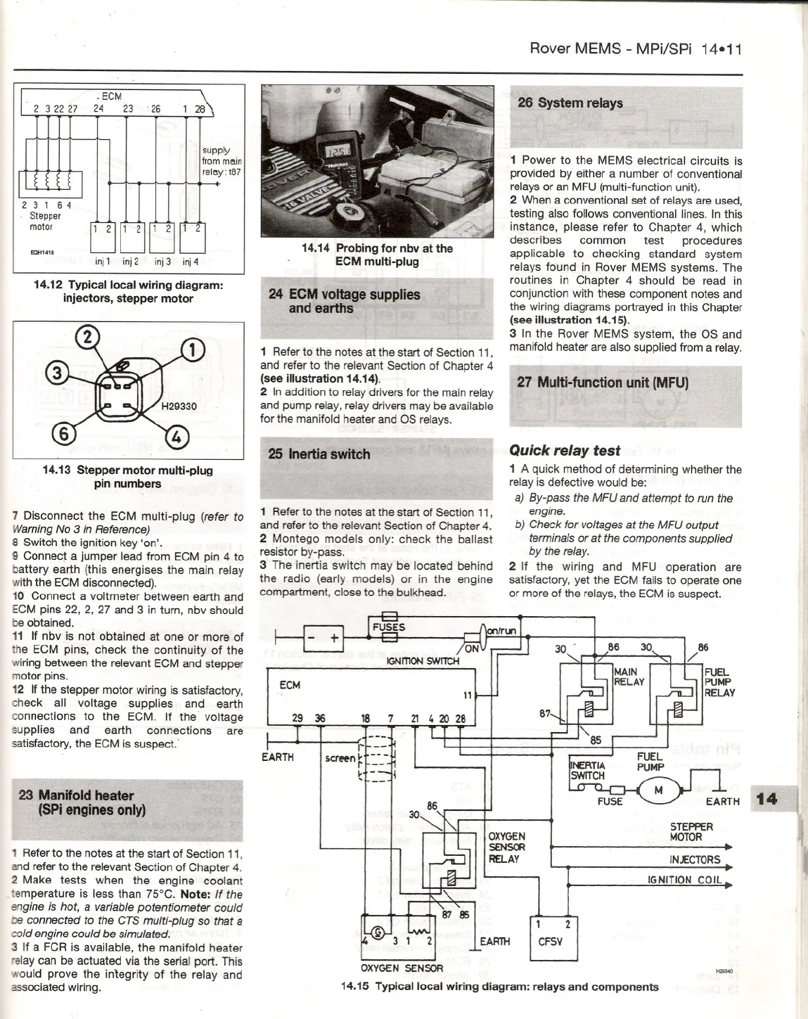
, 26 System relays
.
.
.I
1 Power to the MEMS electrical circuits is
provided by either a number of conventional
relays or an MFU (multi-function unit).
2 When a conventional set of relays are used.
testing also follows conventional lines. In this
instance. please refer to Chapter 4, which
describes common test procedures
applicable to checking standard system
relays found in Rover MEMS systems. The
routines in Chapter 4 should be read in
conjunction with these component notes and
the wiring diagrams portrayed in this Chapter
(see illustration 14.15).
3 In the Rover MEMS system. the OS and
manifold heater are also supplied from a relay.
- _l1li'- 011-
27 Multi-function unit (MFU) ,
J
Quick relay test
1 Aquick method of determining whether the
relay is defective would be:
a) By-pass the MFU and attempt to run the
engine.
b) Check for voltages at the MFU output
terminals or at the components supplied
by the relay.
2 If the wiring and MFU operation are
satisfactory, yet the ECM fails to operate one
or more of the relays, the ECM is suspect.
86 30.
STEPPER
MOTOR
IN.£CTORS
IGNITION COIL
I,
1 2
CFSV
OXYGEN
SENSOR
14.15 Typical local wiring diagram: relays and components


