Rover MEMS - MPi/SPi 14-7
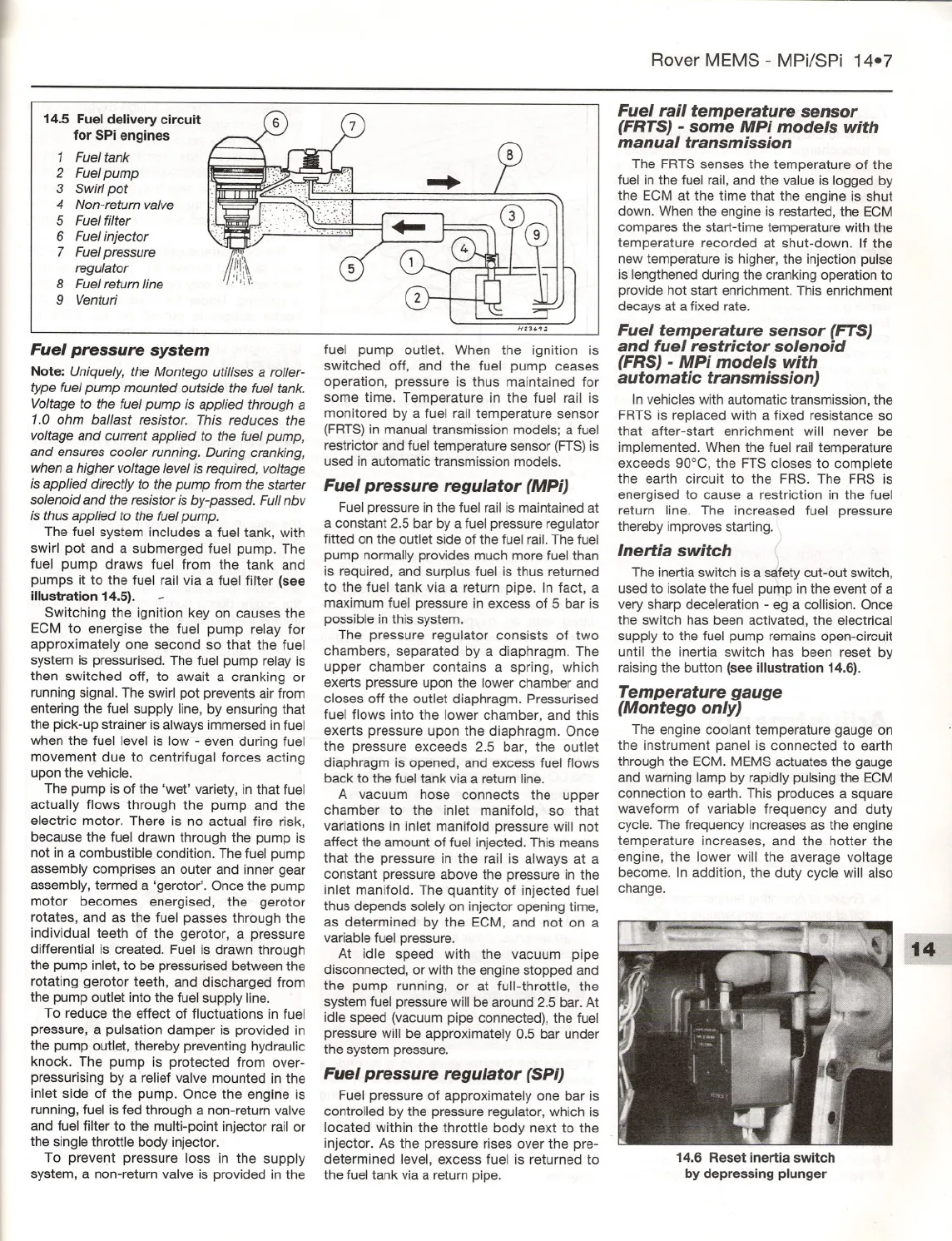
14.5 Fuel delivery circuit
for SPi engines
1
Fuel tank
2 Fuelpump
3 Swirlpot
4 Non-returnvalve
5 Fuelfilter
6 Fuelinjector
7 Fuelpressure
regulator
8 Fuelreturnline
9 Venturi
Fuel pressure system
Note: Uniquely, the Montego utilises a roller-
typefuel pump mounted outside the fuel tank.
Voltageto the fuel
pump is applied through a
1.0 ohm ballast resistor. This reduces the
voltage and current applied to the fuel pump,
and ensures cooler running. Duringcranking,
when a higher voltage level is required, voltage
is applied directlyto the pump from the starter
solenoid and the resistor is by-passed. Full nbv
is thus applied to the fuel pump.
The fuel system includes a fuel tank, with
swirl pot and a submerged fuel pump. The
fuel pump draws fuel from the tank and
pumps it to the fuel rail via a fuel filter (see
illustration 14.5). -
Switching the ignition key on causes the
ECM to energise the fuel pump relay for
approximately one second so that the fuel
system is pressurised. The fuel pump relay is
then switched off, to await a cranking or
running signal. The swirl pot prevents air from
entering the fuel supply line, by ensuring that
the pick-up strainer is always immersed in fuel
when the fuel level is low - even during fuel
movement due to centrifugal forces acting
upon the vehicle.
The pump is of the 'wet' variety, in that fuel
actually flows through the pump and the
electric motor. There is no actual fire risk,
because the fuel drawn through the pump is
not in a combustible condition. The fuel pump
assembly comprises an outer and inner gear
assembly, termed a 'gerotor'. Once the pump
motor becomes energised, the gerotor
rotates, and as the fuel passes through the
individual teeth of the gerotor, a pressure
differential is created. Fuel is drawn through
the pump inlet, to be pressurised between the
rotating gerotor teeth, and discharged from
the pump outlet into the fuel supply line.
To reduce the effect of fluctuations in fuel
pressure, a pulsation damper is provided in
the pump outlet, thereby preventing hydraulic
knock. The pump is protected from over-
pressurising by a'relief valve mounted in the
inlet side of the pump. Once the engine is
running, fuel is fed through a non-return valve
and fuel filter to the multi-point injector rail or
the single throttle body injector.
To prevent pressure loss in the supply
system, a non-return valve is provided in the
fuel pump outlet. When the ignition is
switched off, and the fuel pump ceases
operation, pressure is thus maintained for
some time. Temperature in the fuel rail is
monitored by a fuel rail temperature sensor
(FRTS)in manual transmission models; a fuel
restrictor and fuel temperature sensor (FTS)is
used in automatic transmission models.
Fuel pressure regulator (MPi)
Fuel pressure in the fuel rail is maintained at
a constant 2.5 bar by a fuel pressure regulator
fitted on the outlet side of the fuel rail. The fuel
pump normally provides much more fuel than
is required, and surplus fuel is thus returned
to the fuel tank via a return pipe. In fact, a
maximum fuel pressure in excess of 5 bar is
possible in this system.
The pressure regulator consists of two
chambers, separated by a diaphragm. The
upper chamber contains a spring, which
exerts pressure upon the lower chamber and
closes off the outlet diaphragm. Pressurised
fuel flows into the lower chamber, and this
exerts pressure upon the diaphragm. Once
the pressure exceeds 2.5 bar, the outlet
diaphragm is opened, and excess fuel flows
back to the fuel tank via a return line.
A vacuum hose connects the upper
chamber to the inlet manifold, so that
variations in inlet manifold pressure will not
affect the amount of fuel injected. This means
that the pressure in the rail is always at a
constant pressure above the pressure in the
inlet manifold. The quantity of injected fuel
thus depends solely on injector opening time,
as determined by the ECM, and not on a
variable fuel pressure.
At idle speed with the vacuum pipe
disconnected, or with the engine stopped and
the pump running, or at full-throttle, the
system fuel pressure will be around 2.5 bar. At
idle speed (vacuum pipe connected), the fuel
pressure will be approximately 0.5 bar under
the system pressure.
Fuel pressure regulator (SPi)
Fuel pressure of approximately one bar is
controlled by the pressure regulator, which is
located within the throttle body next to the -
injector. As the pressure rises over the pre-
determined level, excess fuel is returned to
the fuel tank via a return pipe.
Fuel rail temperature sensor
(FRTS)
-some MPi models with
manual transmission
The FRTS senses the temperature of the
fuel in the fuel rail, and the value is logged by
the ECM at the time that the engine is shut
down. When the engine is restarted, the ECM
compares the start-time temperature with the
temperature recorded at shut-down. If the
new temperature is higher, the injection pulse
is lengthened during the cranking operation to
provide hot start enrichment. This enrichment
decays at a fixed rate.
Fuel temperature sensor (FTS)
and fuel restrictor solenoid
(FRS) -MPi models with
automatic transmission)
In vehicles with automatic transmission, the
FRTS is replaced with a fixed resistance so
that after-start enrichment will never be
implemented. When the fuel rail temperature
exceeds 90°C, the FTS closes to complete
the earth circuit to the FRS. The FRS is
energised to cause a restriction in the fuel
return line. The increased fuel pressure
thereby improves starting.
Inertia switch
The inertia switch is a safety cut-out switch,
used to isolate the fuel pump in the event of a
very sharp deceleration - eg a collision.Once
the switch has been activated, the electrical
supply to the fuel pump remains open-circuit
until the inertia switch has been reset by
raising the button (see illustration 14.6).
Temperature gauge
(Montego only)
The engine coolant temperature gauge on
the instrument panel is connected to earth
through the ECM. MEMS actuates the gauge
and warning lamp by rapidly pulsing the ECM
connection to earth. This produces a square
waveform of variable frequency and duty
cycle. The frequency increases as the engine
temperature increases, and the hotter the
engine, the lower will the average voltage
become. In addition, the duty cycle will also
change.
14.6 Reset inertia switch
by depressing plunger


