Rover MEMS -MPi/SPi 14-5
present in sequential systems), each injector
is actuated as its inlet valve opens, in firing
order.
s
Single-point fuel injection (SPi)
The SPi system consists of a single injector
mounted in the throttle body. The amount of
fuel delivered by the injector is determined by
the fuel pressure and the injector opening
time -otherwise known as the pulse duration.
In SPi engines, fuel is injected into the inlet
manifold, where it mixes with air. The
depression produced by a descending piston
causes the resulting air/fuel mixture to be
drawn into each cylinder. Otherwise, operation
Ott{1einjector is very similar to operation of the
inje~d to the MPi systems.
Cylinder identification sensor
(sequential injection only)
. In simultaneous MPi systems, the ECM
does not have to recognise No 1 cylinder, or
ind~ed even the firing order. When the
crankshaft or distributor provides a timing
signal, the correct cylinder is identified by the
mechanical position of the crankshaft,
camshaft, valves and ignition rotor.
On models fitted with sequential injection,
the ECM must determine which cylinder is on
its firing stroke, and the CID sensor provides
the appropriate signal. The CID sensor
operates on the inductive principle, and is a
permanent magnet device mounted adjacent
to the camshaft. A reluctor is attached to the
camshaft, divided into four equal quadrants.
Each quadrant contains a unique number of
teeth, numbering from one to four. Because
the AC-generated signal from each quadrant
is unique, the ECM is able to determine the
camshaft position and cylinder sequence.
The reluctor should be handled with
extreme care, due to the fragile sintered
material used in its construction. Any impact
may cause cracking or a stress fracture.
MAP sensor
r
rE
~
Ir
, s
rE
~
~
ar:
e
1-:::'-
g-e
p
s
I:ec
'Cc
~E
)r fa"'
tsc
The main engine load sensor is the MAP
sensor. A vacuum hose connects the MAP
sensor (located within the ECM) and the inlet
manifold (see illustration 14.2). Manifold
vacuum acts upon the MAP sensor
diaphragm, and the ECM converts the
pressure into an electrical signal. MAP is
calculated from the formula: Atmospheric
Pressure less Manifold Pressure = Manifold
Absolute Pressure.
Using the speed/density method, MEMS
calculates the AFR from the MAP signal and
the speed of the engine (CAS). This method
relies on the theory that the engine will draw in
a fixed volume of air per revolution.
The.inlet manifold on the MPi models is a
'dry' manifold. Since fuel does not enter the
manifold - due to injection being made onto
the back of the inlet valve, there is no risk of
fuel being drawn into the MAP sensor to
contaminate the diaphragm, and a fuel trap is
not used. However, on Rover 820 models
Clad
s are
IQ ne
tg~e
Of a
rde'
tr-e
~ .a
inS.
i~"a:
ster""
r" tt"e
0'"
I
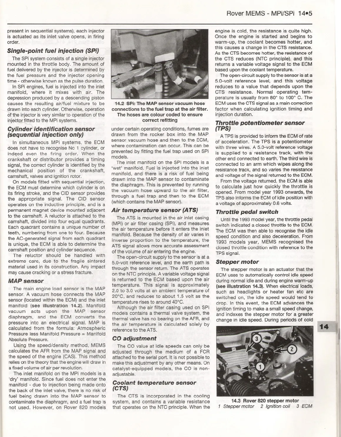
14.2 SPi: The MAP sensor vacuumhose
connections to the fuel trap at the air filter.
The hoses are colour coded to ensure
correct refitting
under certain operating conditions, fumes are
drawn from the rocker box into the MAP
sensor vacuum hose and then to the ECM,
where contamination can occur. This can be
prevented by fitting the fuel trap used on SPi
models.
The inlet manifold on the SPi models is a
'wet' manifold. Fuel is injected into the inlet
manifold, and there is a risk of fuel being
drawn into the MAP sensor to contaminate
the diaphragm. This is prevented by running
the vacuum hose upward to the air filter,
through a fuel trap and then to the ECM
(which contains the MAP sensor).
Air temperature sensor (ATS)
The ATS is mounted in the air inlet casing
(MPi) or air filter casing (SPi), and measures
the air temperature before it enters the inlet
manifold. Because the density of air varies in
inverse proportion to the temperature, the
ATS signal allows more accurate assessment
of the volume of air entering the engine.
The open-circuit supply to the sensor is at a
S.O-volt reference level, and the earth path is
through the sensor return. The ATS operates
on the NTC principle. A variable voltage signal
is returned to the ECM based upon the air
temperature. This signal is approximately
2.0 to 3.0 volts at an ambient temperature of
20°C, and reduces to about 1.S volt as the
temperature rises to around 40°C.
Although the air filter casing used on SPi
models contains a thermal valve system, the
thermal valve has no bearing on the AFR, and
the air temperature is calculated solely by
reference to the ATS.
CO adjustment
The CO value at idle speeds can only be
adjusted through the medium of a FCR
attached to the serial port. It is not possible to
make this adjustment by any other means. On
catalyst-equipped models, the CO is non-
adjustable.
Coolant temperature sensor
(CTS)
The CTS is incorporated in the cooling
system, and contains a variable resistance
that operates on the NTC principle. When the
engine is cold, the resistance is quite high.
Once the engine is started and begins to
warm-up, the coolant becomes hotter, and
this causes a change in the CTS resistance.
As the CTS becomes hotter, the resistance of
the CTS reduces (NTC principle), and this
returns a variable voltage signal to the ECM
based upon the coolant temperature.
The open-circuit supply to the sensor is at a
S.O-volt reference level, and this voltage
reduces to a value that depends upon the
CTS resistance. Normal operating tem-
perature is usually from 80° to 100° C. The
ECM uses the CTS signal as a main correction
factor when calculating ignition timing and
injection duration.
Throttle potentiometer sensor
(TPS)
A TPS is provided to inform the ECM of rate
of acceleration. The TPS is a potentiometer
with three wires. A S.O-volt reference voltage
is supplied to a resistance track, with the
other end connected to earth. The third wire is
connected to an arm which wipes along the
resistance track, and so varies the resistance
and voltage of the signal returned to the ECM.
From the voltage returned, the ECM is able
to calculate just how quickly the throttle is
opened. From model year 1993 onwards, the
TPS also informs the ECM of idle position with
a voltage of approximately 0.6 volts.
Throttle pedal switch
Until the 1993 model year, the throttle pedal
switch indicated a closed throttle to the ECM.
The ECM was then able to recognise the idle
speed condition and also deceleration. From
1993 models year, MEMS recognised the
closed throttle condition with reference to the
TPS signal.
Stepper motor
The stepper motor is an actuator that the
ECM uses to automatically control idle speed
during normal idle and during engine warm-up
(see illustration 14.3). When electrical loads,
such as headlights or heater fan etc are
switched on, the idle speed would tend to
drop. In this event, the ECM advances the
ignition timing to make a small speed change,
and indexes the stepper motor for a greater
change in idle speed. During periods of cold
14.3 Rover 820 stepper motor
1 Stepper motor 2 Ignition coil 3 ECM


