SCION xA/xB Light Enhancement 2006 - INTERIOR LIGHT UPGRADE
Section II – Installation Procedure
Page 6 of 11 pages
PPO
Rev: A 05/10/05
i. The plastic mount faces down.
ii. The threaded metal bracket/plastic mounts
are installed behind the panels.
iii. The screws are threaded from the front of
the panel into the brackets.
6. Tighten the 8-32 screws but be careful not to
over tighten.
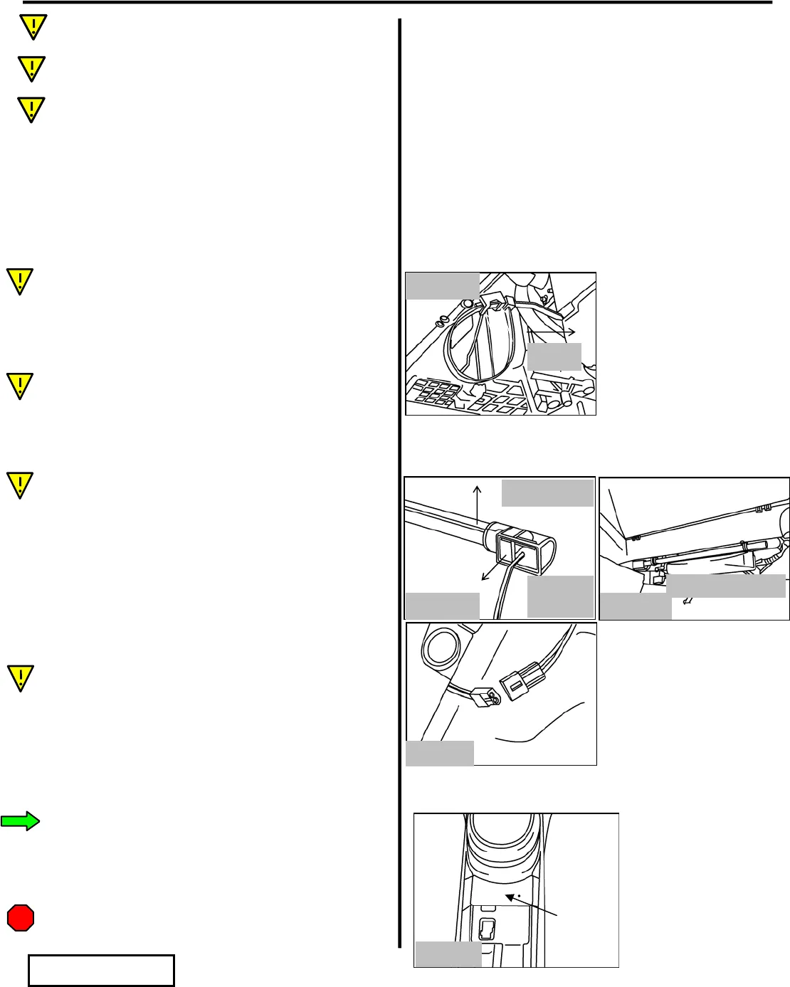
7. Install the Light Guide assembly to the plastic
mounts using the ¼” wire ties.
i. Feed the wire ties into the plastic mounts
from rear to front, orienting the wire tie
“heads” toward the front of the vehicle.
(Fig. G4)
ii. Be sure the wire tie goes through both
“loops” of the plastic mount. (Fig. G4)
iii. Do not fully tighten at this point.
iv. Insert the L/G assemblies into the mounts.
The L/G assemblies should be oriented
with the white “reflector” at the top, the
L/M positioned toward the center of the
vehicle with the wires forward.
(Figs. G5 & G6)
v. Fully tighten the wire ties and cut off
excess.
vi. The L/G can still be re-oriented as desired.
8. Plug the L/M connector into the wire harness
LED pigtail connector. (Fig. G7)
H. Install Switch
1. Align the metal template flush with the bottom
of the pocket and use a center punch/scribe to
mark the center of the hole to be drilled.
(Fig. H1)
i. Do not drill through the template, as the
template could damage the console.
Wires
forward
Fig. G5
Reflector up
Fig. G6
n
r
f
hi
l
Fi
. G7
Front
Fig. G4
STOP
Fi
. H1


