SCION xA 2004 − SECURITY WITH RKE (V3)
Section II − Installation Procedure
Page 6 of 23 pages Supplier Ref #: DIO
Issue: A 06/09/03
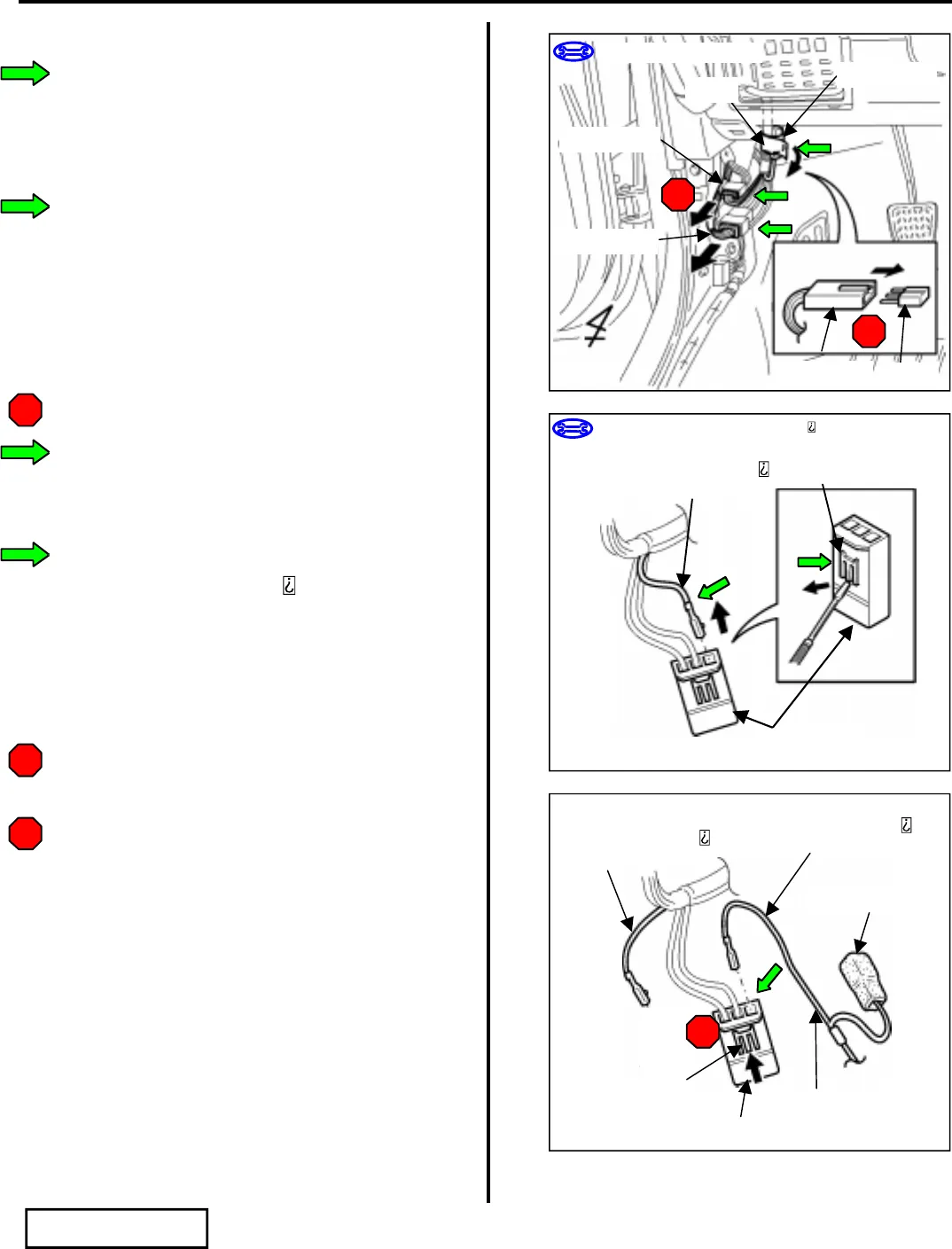
C. V3 Harness Installation
1. Locate the vehicle harness’ white 3P diode
connector and remove the tape securing the
white 3P diode connector to the driver’s side
cowl area. (Fig. C−1)
2. Locate and disconnect the white 13P and 14P
connectors from the driver’s side cowl area.
(Fig. C−1)
3. Using a small flat blade screwdriver, remove
the diode from the white 3P diode connector.
(Fig. C−1)
i. Do not discard the diode.
4. Using a small flat blade screwdriver, lift up the
terminal retainer on the white 3P diode
connector. (Fig. C−2)
5. Locate the RED wire in the right terminal
space. Using a jeweler s screwdriver, release
and pull out the RED wire. (Fig. C−2)
6. Insert the wire at the end of the V3 harness’
RED wire into the right terminal space of the
vehicle harness’ white diode 3P connector.
(Fig. C−3)
i. Verify the correct opening is chosen.
ii. Verify the terminal is inserted and seated
properly.
iii Close the retainer.
iv The terminal should not come out when
pulled lightly from the back. If the
terminal comes off, then push it in more
securely.
STOP
STOP
STOP
Fig. C−1
14P (White)
13P (White)
3P (White)
Tape
STOP
STOP
3P (White)
Diode
Small Flat Blade Screwdriver
Small Flat Blade Screwdriver, Jeweler s Screwdriver
Fig. C−2
Vehicle Harness
RED Wire
Retainer
3P (White)
Fig. C−3
V3 Harness
RED Wire
3P (White)
V3 Harness’ 1P
V3 Harness
Vehicle Harness
RED Wire
STOP
Retainer


