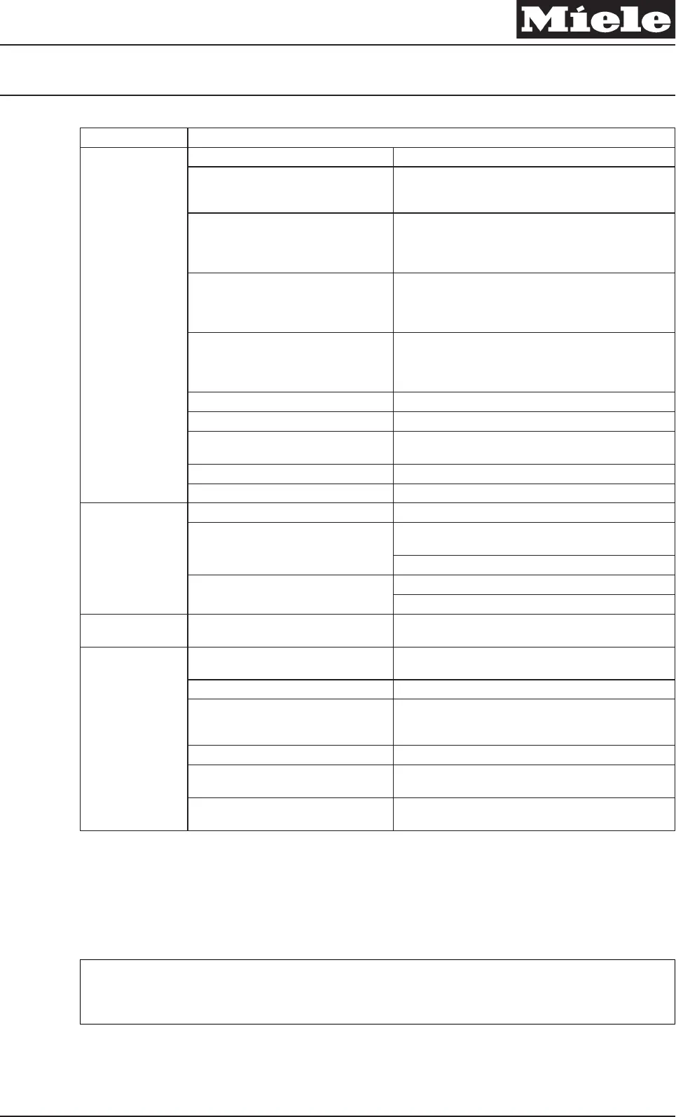
Service function
Component / Sensor
Component test
Components Function check
Water path control (M 24) position 1, only
if present, and water intake valve (Y1 or
Y14 / Y40 with water path control)
Water run over the porthole for 10 seconds
Water path control (M 24) position 2,
water intake valve (Y1 or Y14 / Y40 with
water path control), Heater, Analog
pressure sensor
Water run via compartment I to level I. Heating, starting
at level I, to 95°F (35°C)
Water path control (M 24) position 3,
water intake valve (Y2 or Y14 / Y40 with
water path control), Analog pressure
sensor
Water run via compartment II to level II
Water path control (M 24) position 4,
water intake valve (Y1 and Y3, or Y14 /
Y40 with water path control), Analog
pressure sensor
Water run via compartment III to level III (fabric softener
compartment)
Drain pump (M8) Activate drain pump, drainage independent of level
Motor drum drive (M5) Activate drum, rotation, wash
Motor drum drive (M5). Drain pump (M8) Drum drive, spin speed limited according to program
selection. Drain pump on / Drain valve open.
Drum light (H3/6) (optional) Drum light on
Hot water valve (Y12 / 2Y40) (optional) Water run via compartment II to level III
Sensor test070
2.4.2 Sensor test
Sensors Status
Float switch (B8) in the sump No water in the sump => Float switch not activated =>
Switch closed = > Buzzer on
Float switch activated => Switch open = > Buzzer off
Door contact (A2) Door closed => Switch closed
Door open => Switch open
Operating hours
Power electronic (ELP), refer to 070
2.4.3 Operating hours meter
Indication of operating hours
Operating070 2.4.4
Operating
Keypads Tone to acknowledge when pad is pressed, and the LED
corresponding to the pad lights up.
Buzzer Acoustic signal
Display / LED Test All display items are alternately switched on and off
(flashing). All LEDs, except the PC LED, are switched on
and off (flashing rhythm).
Display Backlight The backlight is switched on and off (flashing rhythm).
System component test control
electronic (EW)
Test result, refer to display
Control dial version: Test the control dial
(DWS)
Program positions are indicated
Table 4: Service Mode Overview
1)
Several faults are shown by pressing the left keypad below the display.
2)
Delete fault memory: Select option “Delete fault memory” and press the right pad (OK) below the display.
Quit (without saving)
x
Note
Delete the fault memory before ending.
A Select service function Exit and confirm.
Descriptive Technical Documentation
DTD no. 11-4800 070-45
22.12.2006, US_am This information should not be duplicated or passed on without Miele approval. All rights reserved.


