Installation
CAUTION: Do not replace the grille from (Figure 28)
with shutters. Do not allow heat to be trapped in the
gravity vent system.
1. Plan the gravity vent run first. Be aware that the max-
imum actual pipe length between the top of the fire-
place and the outlet is 15 feet. There is no maximum
number of elbows in a run, but the run must never go
in a downward direction as this can trap heat in the
gravity vent system.
2. The grille adapter is designed to be installed under-
neath the gypsum board in the wall. In the desired
location, frame a 13" x 13" hole to accept the gravity
vent grille adapter. Fit the gravity vent grille adapter
into the framed hole and fasten it into place with nails
or screws. If you are installing the outlet in an already
finished area, you must remove the gypsum board
and frame a 13" x 13" hole in the existing framing, in
order to meet the required clearances.
3. Remove the outer cover to the left side of the flue out-
let on the Delta.
4. Cut the insulation to the size of the opening and slide
the cover plate underneath to the side (it is taped in
place).
5. Install the B-vent starter section. By putting your hand
up inside and underneath, bend up at least two of the
four tabs at the base of the starter section to hold it
in place.
6. Install the “shut-off” damper in the B-vent starter sec-
tion through the left side louvers. The shut-off damper
enables the manual control of hot air flowing through
the gravity vent pipe. With the top left louver
removed, and the angular portion of the rod in hand,
insert the damper rod into the rear hole in the starter
section. The rod should slide in and down the key-
hole, making sure that the #2 washer and spring on
the control arm are both on the outside of the starter
section and #1 washer is inside the starter section. A
definite tension should exist between the shut off
damper rod and the starter section. Replace the lou-
vers. The damper rod should protrude above the top
of the louvers.
7. Install the B-vent pipe between the B-vent starter and
the grille adapter. Fasten each joint with 3 screws (if
the B-vent pipe manufacturer allows this in their
instruction manual). Insert the B-vent pipe in the grille
adapter and fasten it with three screws. The B-vent
pipe needs only to be inserted into the adapter
enough to be able to screw it in place. This allows
you about 3 ½" of play.
Page 18
DELTA
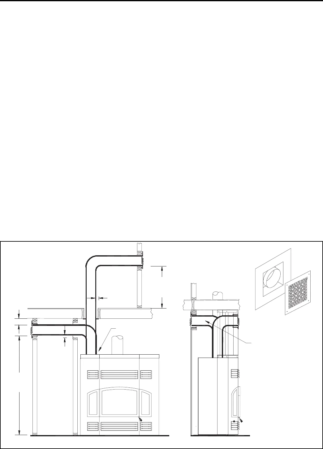
Note: grill is to be oriented
"down" into the room as shown.
59" min.
for child
safety
2" min
4" min
59" min.
for child
safety
2" min
"B"-vent
starter
Figure 28: Gravity vent clearances
optional gravity
vent outlet
"B"- vent grill and adapter