8. Once the wall facing around the gravity vent grille
adapter has been completed, install the grille with the
supplied screws. The gravity vent is now ready for
operation.
THE CENTRAL HEAT SYSTEM
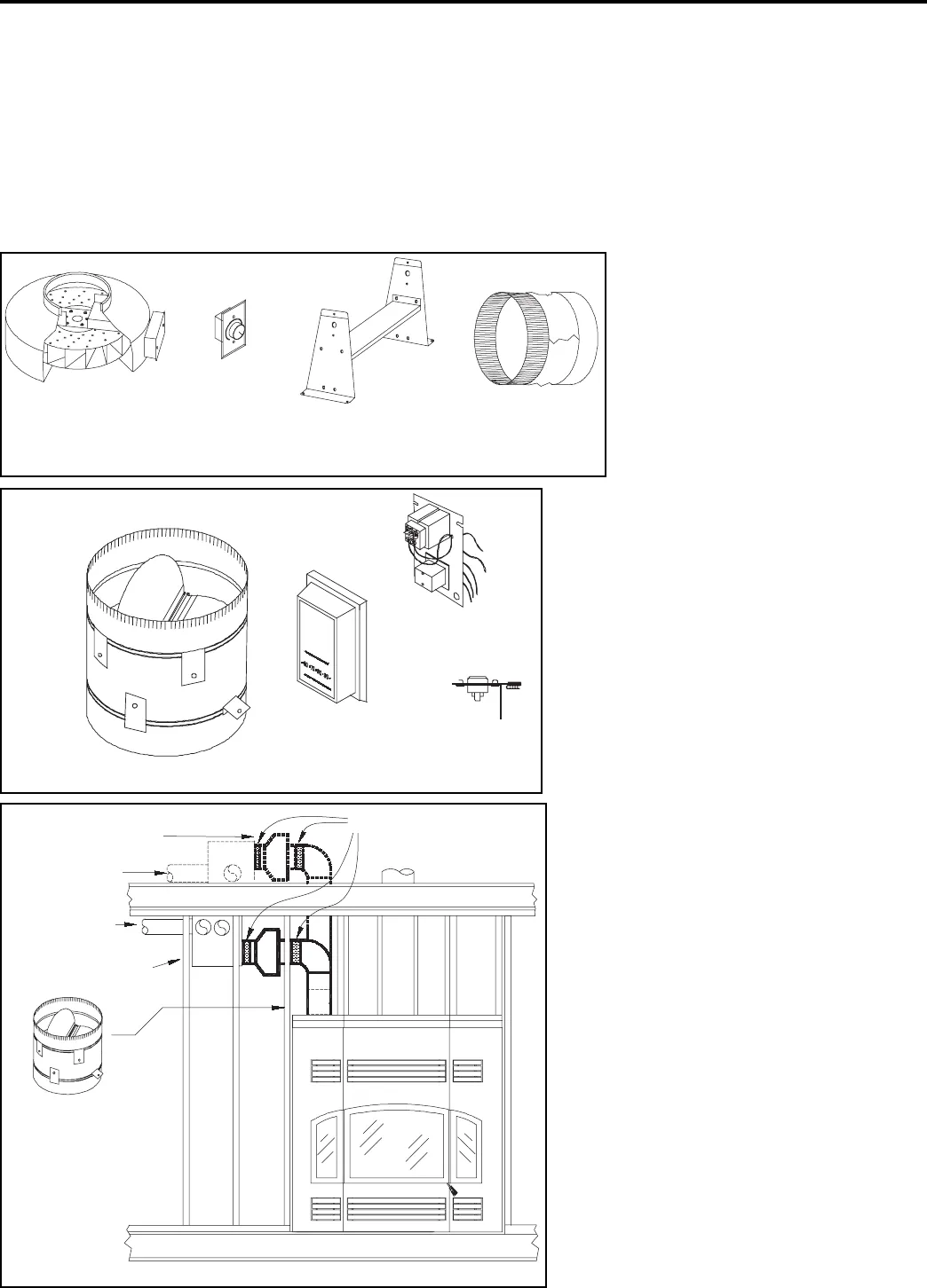
To install the central host option you will need:
1. Part FDHC6: A blower transformer relay, a thermostat
and a thermo disc (Figure 30).
2. Part FDHC6-1: A back draft damper (Figure 30).
3. Part FDHB6: A maximum 636 c.f.m. blower with a
variable speed motor, 2 noise reduction collars, a
blower speed control, and a mounting bracket (Figure
29).
NOTE: Both part numbers must be used together for this
system. Use of any substitutes will decertify the system.
When ducting from the top of the fireplace the 8" back
draft damper prevents hot air from trav-
elling into the ‘C’ vent (single wall) duct-
ing unless the Central Heat Blower
(FDHB6) is operating. When the ther-
mostat calls for heat, the blower turns
on and opens the one-way valve. At the
same time, the room air is drawn
through the upper and lower louvers,
which mixes and reduces the overall
temperature of the forced air that travels
through the ducting.
NOTE: The central heat ducting may be
run at a 0" clearance to combustibles.
Warning: If you are ducting out of the top of
the fireplace and the backdraft damper is not
installed, the central heat ducting will
become too hot for the surrounding com-
bustible materials. Any substitute for any
RSF kit will void all liability and warranty
coverage by RSF Woodburning Fireplaces.
Installation
1. Remove the cover to the left on the top of the
Delta.
2. Cut the insulation to the size of the opening
and slide the cover plate underneath to the
side (it is taped in place).
3. Install the back draft damper crimped side
up, making sure it is pushed all the way
down. Bend out the 4 top tabs once install
bend out the tabs on the lower edge of the
damper in at least 2 places inside the fire-
place with a pair of pliers, so the back draft
damper cannot be pulled out again.
4. Before proceeding with the installation of the
blower,
make sure that the electrical service to the
blower is in the “OFF” position. All wiring
should be in accordance with local ordi-
nances and the National Electric Code.
NOTE: The blower can basically be installed
anywhere in the home. However, some thought
should go into the planning, to ensure that the
Page 19
DELTA
central heat variable
speed blower
blower speed
control
mounting
bracket
noise reduction
collars (2)
Figure 29 : Central heat blower kit (FDHB6)
top tabs
blower transformer
relay
thermostat
thermo disc
Figure 30: Central heating kit (FDHC6 and FDHC6-1)
lower edge
tabs
noise reduction collars
alternate blower
location
2 - 4" or 6"
diameter runs
zero clearance
3 - 6" or 5"
diameter runs
back draft
damper
Figure 31: Central heat location options