must be installed to allow the air to return to the fireplace.
Otherwise periodic smoking from the fireplace will result.
9. Wire the blower to a 115 volt, 15 amp breaker through the
terminal block provided. The variable speed switch pro-
vided should be installed in a convenient location near
the fireplace so the blower can be shut off during refu-
elling. The blower transformer relay should be placed in
an accessible location near the blower. It should be
mounted in a 4x4 electrician’s box. You have two options
of how you can connect the central heat blower to the
blower control assembly. Follow the wiring diagram on
(Figure 42).
a) If you would like the blower to turn on when the ther-
mostat calls for heat, first locate the thermostat in the
principal room heated by the duct system (this is the most
popular use of the central heat blower). Do not install it
in the room where the fireplace is installed. We recom-
mend an electrician wire the following. There are yellow,
black and red wires coming out of the relay as shown in
the wiring diagram. Connect the wire from #4 of the ter-
minal block to the yellow relay wire and the black trans-
former wire with a wire marrette. Connect the black relay
wire to the variable speed switch and leave the red wire
unconnected with a wire marrette attached for protection.
Connect the neutral (the white wire) to the wire from #6
terminal (see Figure 32).
b) If the fireplace is in a small room and/or you would
like the central heat blower to remove air from this room
when it becomes too hot, locate the thermostat in the
room with the fireplace (this is a less common use of the
central heat blower). We recommend an electrician wire
the following. There are yellow black and red wires com-
ing out of the relay as shown in the wiring diagram.
Connect the wire from #4 of the terminal block to the yel-
low relay wire and the black transformer wire with a wire
marrette. Connect the red relay wire to the variable speed
switch and leave the black wire unconnected with a wire
marrette attached for protection. Connect the neutral (the
white wire) to the wire from #6 terminal.
Warning: Do not interchange the variable speed control
between the central heat blower kit and the internal
blower kit.
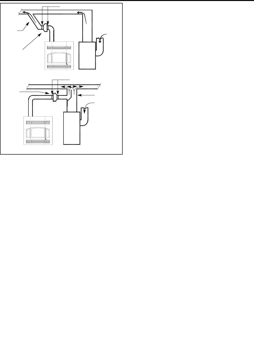
(Figure 31) shows some ways of ducting the hot air from the
blower. You are not restricted in the size of pipe, as long as
the total cross sectional area of all runs combined is not less
than 50 square inches. The diagram shows alternate blower
locations. Only one external blower can be installed.
1. If the blower fails to operate, check the following:
a) Consult the wiring diagram to assure proper con-
nections.
b) To assure proper contact, check the motor lead
wiring, incoming supply wiring, and capacitor connec-
tions.
c) If possible, use a meter to test for continuity
between the fan leads. Please note that the capacitor will
show no reading if it is tested with a meter.
2. If the blower still fails to operate, consult your local RSF
Woodburning Fireplaces authorized dealer for repair or
replacement instructions.
ZONE HEATING (FDHCZ-1 AND FDHCZ-2)
For more regional heat control, the Delta is ideally suited for
zone heating. (Figure 38) shows an example of a three zone
system. The thermostat simultaneously opens the desired
valve and starts the blower when heat is required. The zone
control system consists of:
1 - FDHCZ-1 - 1 control box
(figure 32) - 1 blower transformer relay
- 1 thermo disc
NOTE: The FDHCZ-1 replaces the FDHC6 if you are
installing the zone system.
1 to 3 - FDHCZ-2 - 1 zone valve (normally closed)
(figure 33) - 1 thermostat
The system is wired similarly to the central heat system with
the addition of the control box and the zone heat valve (see
Figure 39). The whole system runs on 24V AC. Make sure
that the thermostats are matched with the correct zone valve.
NOTE: THE Delta MUST BE INSTALLED IN ACCOR-
DANCE WITH ALL LOCAL CODES, IF ANY. IF NOT, FOL-
LOW THE CURRENT CSA C22.1 IN CANADA OR NFPA70
IN USA. INSTALL AND USE AS PER THE MANUFACTUR-
ER'S INSTALLATION AND OPERATING INSTRUCTIONS.
Page 21
DELTA
45° tie-in
central heat
blower
cold air
return
central heat
blower
noise reduction collars
noise reduction collars
deflector
Figure 33 : Example tie-in to central heat plenum
furnace
cold air
return
furnace