FRAMING IN
The enclosure walls can be framed with any suitable
materials (2x4 or 2x6 studs, plywood, gypsum board,
etc.). Because of the high heat output potential of the
Delta, combustible material must NOT go closer to the
fireplace than the stand-offs, top, back and sides. You
may also completely cover the top of the Delta as long as
you maintain top standoff clearances and the 2" clear-
ances around the chased chimney. The 2"
clearance around the chimney must be
open to the fireplace up to the first fire stop
(39½" min.).
SPARK GUARD
Install a 5" piece of sheet metal centred
under the joint between the fireplace and
the hearth extension (see Figure 15). This
is required under the centre door only (pro-
vided). This will make certain that sparks
cannot lodge in the crack and start a fire. If
you are preparing a raised fireplace, then a
“Z” shaped spark guard must be installed.
The height of the Z-shaped hearth guard
must equal the distance between the floor
and the base of the unit. The minimum
depth the spark guard must extend beneath
the Delta is 2 ½ inches.
(Z-SHAPED GUARD
NOT SUPPLIED).
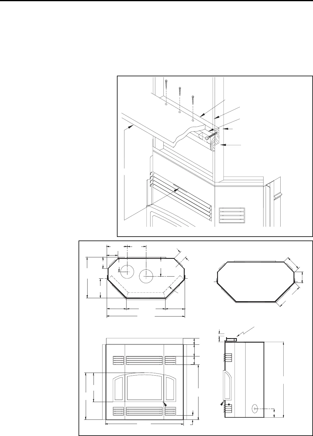
MANTEL
A masonry or other non-
combustible mantle may be
placed directly above the top
louvers. If a wood or other
combustible mantle is
desired, then it must be at
least 10 1/2 inches above
the top louver opening (see
Figures 16 and 17). No com-
bustible material is to be put
under mantle.
HEARTH EXTENSION
The area immediately in
front of the fireplace must be
protected by a non-com-
bustible material such as
brick, tile, stone, or slate.
The protection must extend
at least 16" in front and 8" on
both sides of the fireplace
opening (see Figure 16).
There is no minimum thick-
ness required for the hearth
extension.
Page 13
DELTA
10½" min.
screws attach mantle to crown moulding
(countersink and fill)
Figure 17: Installation of mantles and crown moulding
backing 2x4
corner moulding hides mounting
screws/bolts
screw/bolt attaches crown moulding
to backing 2x4 (counter sink and fill)
crown moulding
11½”
6¾”
12”
25½”
4¼”
12”
23 ½”
47 ¼”
11 7/8”
11 7/8”
12½”
8½”
6¾”
16¾”
2½”
5”
5”
35”
3”
29¾”
19”
45”
2½”
framing guide
5½”
Figure 18: Unit dimensions
47 ¼”