VoloAccess™ User Manual
Copyright © Vololink Pty Ltd 2006-2010 V1.43 July 2010 Page 8 of 78
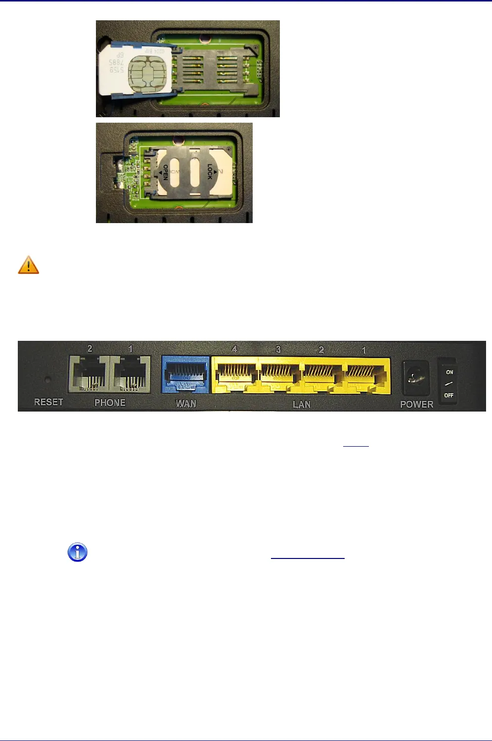
Slide the SIM into the retainer with the cut
corner positioned as shown.
The contact pads on the SIM should be
facing up ready to engage the connectors
in the base of the holder.
Turn the retainer over and slide in the LOCK
direction to secure the SIM in position.
Complete installing the SIM by:
replacing the SIM compartment cover, and
refitting the side panel.
Removing the SIM
Before attempting to remove the SIM, disconnect the power supply.
To remove the SIM simply perform the above steps in the reverse order.
VoloAccess Connections
The following image shows the rear panel of the VoloAccess and describes the purpose of each connection.
Reset button – Use a paper clip to reset the VoloAccess. See below for further information on
resetting the VoloAccess.
Phone ports – Connect a phone here (Voice enabled models only).
By default, the WAN port can be used as a LAN port. In this configuration the VoloAccess is a
five port switch. If the WAN port is configured to connect the VoloAccess to an external
modem for alternative WAN access, the VoloAccess is then a four port switch.
The WAN port can be disabled. See Operating Mode under Settings on the WAN
Ethernet page for further information.
Ethernet ports (LAN) – Connect locally attached computers here.
Power supply – Connect the power supply cable here. Use the adjacent switch to turn the
VoloAccess On/Off.
* The two phone ports on the VoloAccess share a common phone line. If two phones are connected to the
VoloAccess, the first handset lifted will get the line and can place a call. While a call is in progress, any
attempt to make a call from the second phone results in the busy signal. For inbound calls, both phones
ring – the first handset lifted will take the call; the other handset receives the busy signal.


