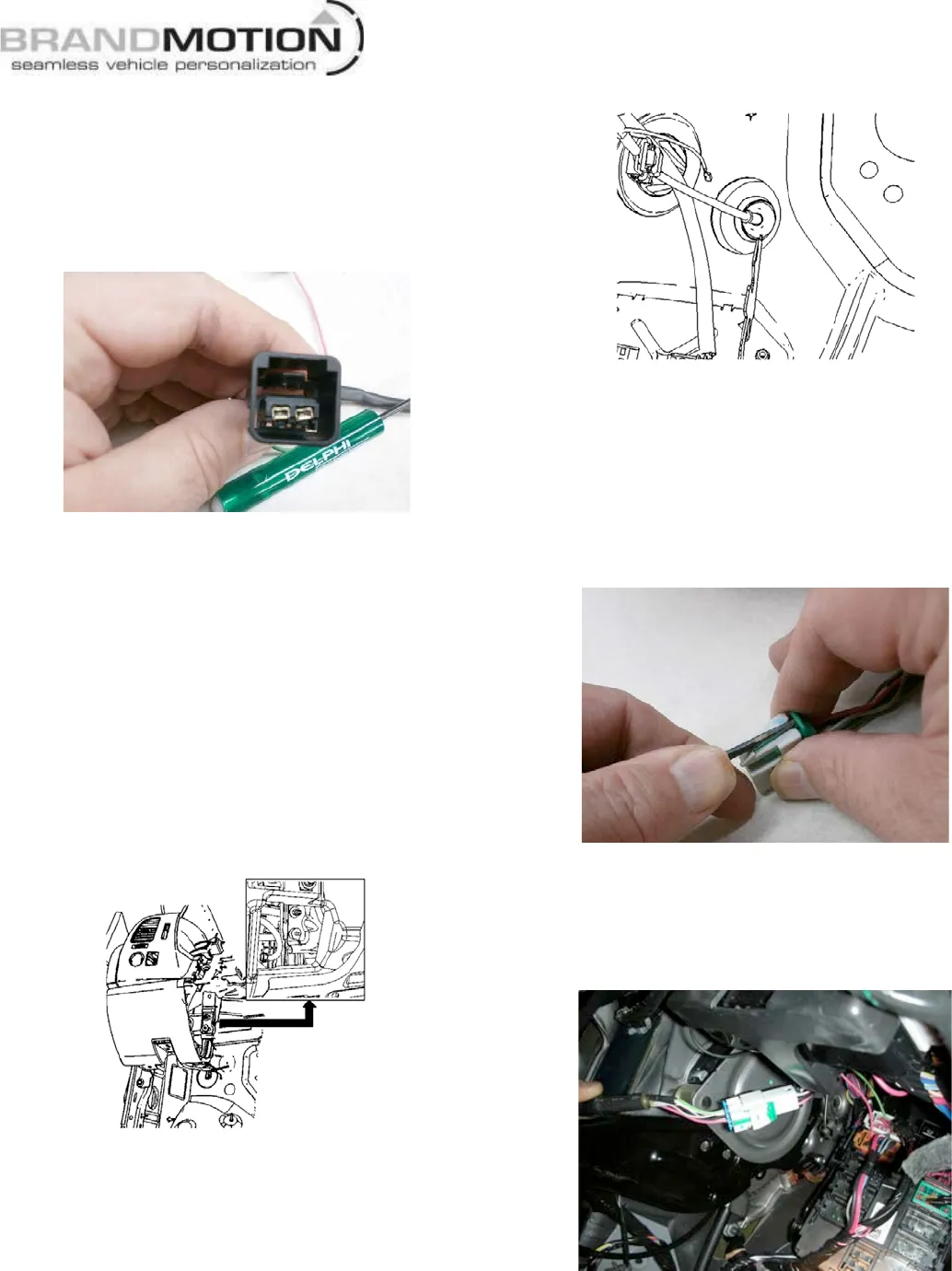
• Use Delphi Terminal Tool 12094429 or a small flat
blade screwdriver to press the terminal of the blue
wire into the connector. NOTE: the terminal fits
tightly initially, and when it goes into the slot it often
slides in too far. If this occurs, the terminal must be
backed up to sit flush with the terminal from the
green wire. Figure 30.
FIGURE 30
• Slide gray TPA inside the black connector to lock
green and blue wires into place.
• Snap the supplied Jumper Harness into black
connector on the supplied NAV Harness. Figure
27. Then, connect the green wire of the Jumper
Harness to cavity 5 of the C11 connector (where
blue wire was removed).
56. Re-insert TPA and C11 Connector into M-BEC. Figure
25.
57. Locate the Ground ring terminal on the black wire of
the NAV Harness and attach at lower fastener of
knee bolster support, using the supplied Ground Nut
and a 10mm socket. Tighten to 4 N·m (36 lb in).
Figure 31.
FIGURE 31
Install Chassis Harness
58. Locate the supplied Chassis Harness.
59. Route the grommet-end of the Chassis Harness
through the Driver’s Side Wheel Housing and then
through the opening in the Front of Dash. Figure 32.
FIGURE 32
60. From the inside of the cab, pull the Chassis Harness
through until the grommet is properly seated.
61. Remove the green lock tab from the Chassis
Harness front connector by inserting the tip of
Delphi Terminal Tool 12094429
or a small flat blade
screw driver between the lock tab and connector
and prying the tab out. (Figure 33)
FIGURE 33
62. Connect the Chassis harness to the NAV Harness
then reinstall the green lock tab. Secure both
harnesses to vehicle wiring with supplied Wire Ties.
Figure 34.
FIGURE 34
63. Install the MBEC into Support Bracket. Figure 35.