OPERATING MANUAL
7
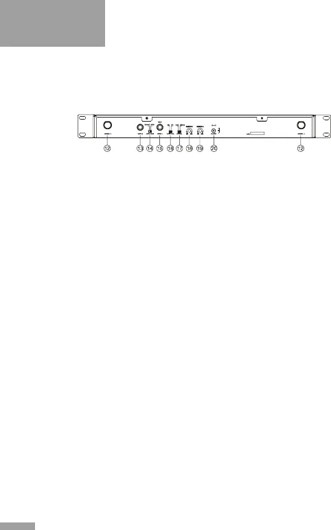
12) Antenna Connectors
13) Output B: ¼” unbalanced jack output connector for CH B.
14) O UTPUT M OD E Swi tc h: Use “ M I X ED ” to o u t p u t
both microphones from output A . Use “SEPARATE”
to output each microphone individually.
15) Output A: ¼” unbalanced jack output connector for CH A
or the mixed signal.
16) Output Level Switch: Use “MIC” when connected to
microphone inputs (-14dBv/ 100Ω). Use “LINE” when
connected to line level inputs (+4dBv/ 5kΩ).
17) LOC K: W hen engage d a ll fro nt pane l but tons are
disabled. The power switch will continue to function even
when the unit is locked.
18) SQUELCH B: Adjusts the sensitivity of Channel B to
reduce noise.
19) SQUELCH A: Adjusts the sensitivity of Channel A to
reduce noise.
20) DC Power receptacle: For connecting the external
13V DC power supply (centre pin positive).
REAR PANEL OF THE DUAL CHANNEL RECEIVER:
Fig.2


