6
Contact 502A
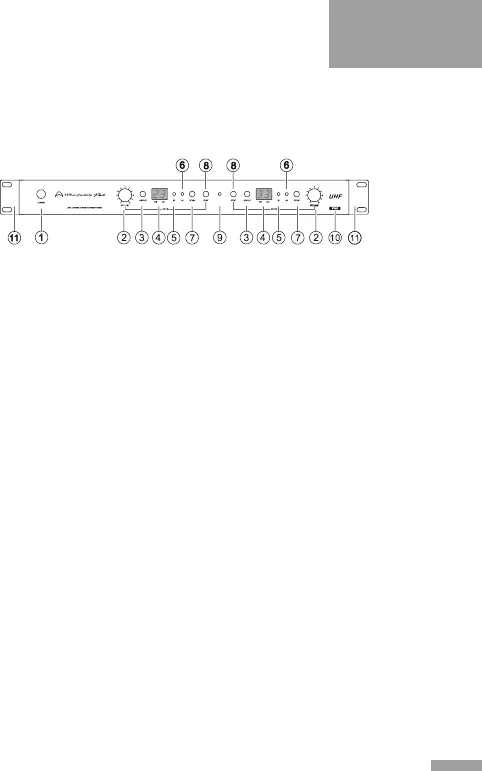
FRONT PANEL OF THE DUAL CHANNEL RECEIVER:
Fig.1
1) POWER: Toggles the power on and off.
2) VOLUME CONTROL (Channels A & B): Sets the level
for each channel.
3) G R O U P ( C h a n n e l s A & B) : C r e a t e g r o u p s of
microphones, which is useful when many microphones
are used simultaneously.
4) LED (Channe ls A & B): Displays t he GRO UP and
CHANNEL assignment for each channel.
5) RF LED (Channels A & B): Indicates that RF signal is
present and locked.
6) AF LED (Channels A & B): Indicates that audio signal is
present.
7) SCAN (Channels A & B): Initiates scanning for a new
channel. Automatically scans and locks on to compatible
interference free channels.
8) SYNC (Channels A & B): Synchronises the transmitter to
the receiver.
9) IR SYNC receiver: Receives the IR SYNC signal from
the base of the transmitter.
10) Receiver Frequency Codes. (See page 14,
III
Frequency Range Code Table)
11) Rack ears: Used to fix the receiver to a standard 19’’
equipment rack.


