7
j. Adjust the inlet pipe and coupler for best tment. Make sure the AEM
®
intake system does not come into contact with
the vehicle anywhere. Adjust coupler at throttle body to ensure that both the throttle body and the AEM
®
inlet pipe are
seated ush up to the lip inside the coupler. Tighten the hose clamps and lock nut on the rubber mount.
k. Reinstall lower splashguard and plastic fender liner using the original factory hardware. Remove jack stands and lower
vehicle.
NOTE: Failure to install the plastic splashguard and fender liner will result in diminished performance and
increase the potential for engine damage due to water ingestion in rainy conditions.
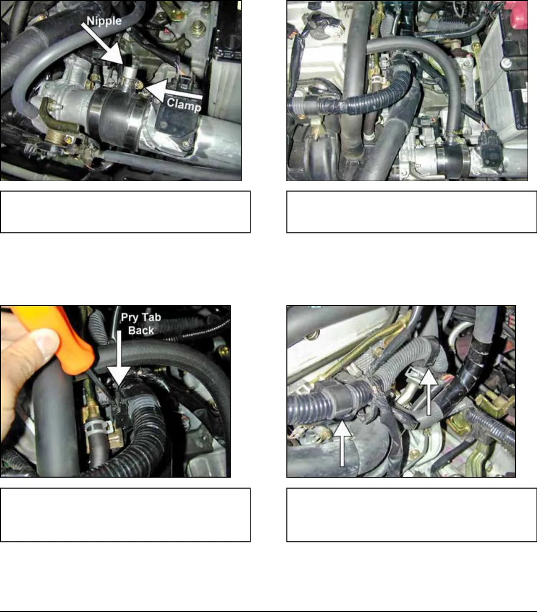
l. Install the supplied vacuum nipple into the throttle
body coupler. Secure the nipple with the supplied
hose clamp.
m. Install the supplied breather hose between the
nipple on the throttle body coupler and the valve cov-
er. Secure the hose with the original spring clamps.
NOTE: Due to manufacturing variances, it is sometimes necessary to adjust the main engine
wiring harness to allow the harness to reach the MAF sensor. If there is any tension on the
MAF sensor wires at all, follow the instructions below. If there is a sufcient amount of slack
in the harness, skip ahead to step 3q.
n. Gently pry back the plastic tab and remove the
plastic clip on the wire harness from the metal bracket
next to the valve cover. The clip will lift straight up off
of the bracket.
o. Repeat for the next plastic clip on the wire harness
towards the rewall.


