SAMSUNG CLP-510 TONER CARTRIDGE REMANUFACTURING INSTRUCTIONS Page 4
USA Sales: T 800.221.3516 F 888.791.9188
International Sales: T +1 631.590.1040 F +1 631.218.3285
www.summitechnologies.com
In the third stage, the laser beam is fired onto a rotating
mirror (called the scanner). As the mirror rotates, the
beam is reflected into a set of focusing lenses. The
beam then strikes the drums surface, neutralizing the
negative charge and leaving a latent electrostatic image
on the drum. The areas where the laser did not strike
the drum will retain the negative charge. See Figure 4
The fourth or developing stage is where the toner is
developed on the drum by the developing section (or
supply chamber), which contains the toner particles. The
development stage is actually made up of two steps:
toner charging, and the actual development. In the toner
charging stage, the toner stirring blade turns inside the
hopper. As it turns, friction causes a negative potential
to develop on the toner. In addition, a toner charging
roller also places a negative voltage on the toner. These
two charges ensure a uniform charge on the toner.
Once the toner is properly charged, the toner will coat
the developer roller. The toner will also be held onto the
developer roller by another negative DC bias voltage.
This voltage is controlled by the printer’s intensity
setting, and causes either more or less toner to be
attracted by the developer roller. This in turn will either
increase or decrease the print density. The toner is first
fed to the developer roller by the feed mechanism,
which in this case is an open-cell foam roller. The
amount of toner on the developer roller is controlled by
the doctor blade, which uses pressure to keep the
amount of toner on the roller constant.
As the laser exposed areas of the OPC Drum approach
the developer roller, the toner particles are attracted to
the drum’s surface due to the opposite voltage
potentials of the toner, and laser exposed areas of the
OPC drum. See Figure 5
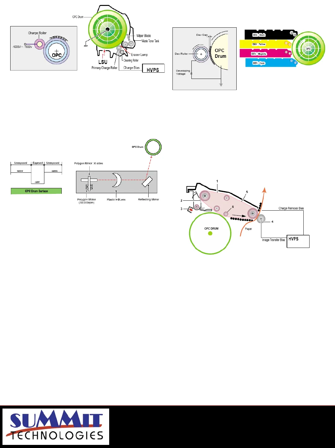
The fifth stage is the transfer stage. This is where there
are some large differences from monochrome printers.
A pre transfer lamp illuminates and reduces the
adhesion of the toner to the OPC drum and allows a
better transfer to the Image transfer belt or ITB. The
different color latent images are then transferred from
each toner cartridge to the ITB in a specific sequence.
First the yellow is transferred, then the magenta is built
up on top of the yellow followed by the cyan and black.
The full image on the ITB is then transferred to the
paper using the T2 transfer roller. See Figure 6
In the sixth stage, the image is then fused onto the
paper by the fuser assembly. The fuser Assembly is
comprised of 2 heat rollers. This is a bit different from
other systems. There is a fixed upper heat roller with a
500W lamp inside, and a spring loaded lower heat roller
with a 300W lamp inside. This system ensures proper
fusing in all print conditions. (Remember, these
machines come with built in duplex). See Figure 7
The final stages are where the ITB belt and drum are
cleaned.
The OPC drum is cleaned after every complete image
has been transferred to the ITB, and the ITB is cleaned
after every complete image has been transferred to the
paper. A cleaning solenoid activates and a cleaning
blade removes the waste toner from the ITB. The waste
toner is transferred to the waste toner tank
Figure 3
Figure 4
Figure 5
Figure 6


