P/N: 4FT020-010
©2002 Vortech Engineering, LLC
All Rights Reserved, Intl. Copr. Secured
07FEB02 V2.0
(99-01SuperDuty(4FT V2.0))
11
10. MOUNTING BRACKET BRACKET & SUPERCHARGER INSTALLATION, cont’d.
11. AIR INLET ASSEMBLY
J. Thread the 1/8" NPT x #4 x 90° fitting into the oil
feed fitting on the supercharger. Rotate the
fitting down. Connect the oil feed line to the #4
fitting and tighten. Use only clean engine oil on
the oil feed fittings threads.
K. Secure the oil feed line away from heat and
abrasion with the provided tie wraps.
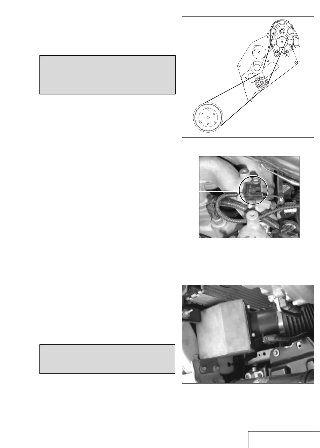
L. Route the supplied supercharger drive belt
around the crank pulley, supercharger drive
pulley and grooved idler. Using a 1/2" drive
breaker bar, rotate the spring tensioner clock-
wise and align the belt. (See
Fig 10-d
.)
M. Relocate the capacitor (previously attached to
the upper front cover mounting stud) to one of
the screws securing the water neck or upper
manifold. (See
Fig 10-e
.)
A. Attach the MAF meter to the MAF bracket using
the supplied 1/4” hardware. Slide the air filter
onto the tube of the MAF bracket. Using a 5/16”
nut driver or socket, reach in through one of the
Ø5/8” holes and tighten the hose clamp. Cover
the holes with the provided finishing plugs.
B. Install the MAF assembly onto the driver’s side
of the core support using the factory hardware.
(See
Fig. 11-a
.)
C. Reconnect the MAF wiring connector to the
MAF meter.
D. Install the Ø3.5” x 2” silicone sleeve and #56
hose clamps onto the supercharger inlet. Install
the cast aluminum inlet duct into the silicone
sleeve and tighten the hose clamps.
NOTE: The thick rubber mat may need to be
unsnapped and folded over toward the
radiator to allow proper mounting of
the MAF assembly.
Fig. 10-d
Fig. 10-e
See Appendix A-6
for detail view.
?
CAPACITOR
Fig. 11-a
NOTE: Do not use any type of sealant on the
oil feed fittings. It may become dis-
lodged and clog the oil feed orifice,
causing premature failure of the super-
charger and voiding your warranty.


