P/N: 4FT020-010
©2002 Vortech Engineering, LLC
All Rights Reserved, Intl. Copr. Secured
07FEB02 V2.0
(99-01SuperDuty(4FT V2.0))
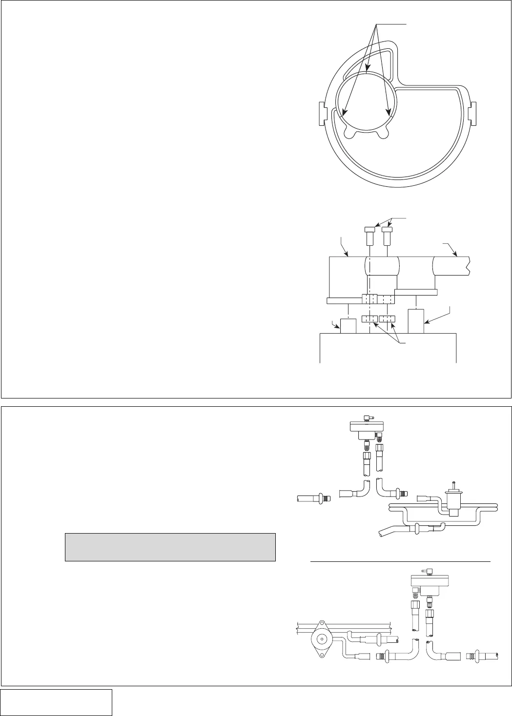
8. FUEL MANAGEMENT UNIT (FMU) INSTALLATION
A. Using a 3/8" springlock disconnect tool, discon-
nect the fuel return line at the back of the engine
on V-10 models (See
Fig. 8-a
) or drivers side
valve cover on V-8 models (See
Fig. 8-b
).
B. Following the diagram connect the 17" male
FMU inlet line to the fuel rail. Route the fuel line
to the -4 x 90° brass fitting on the FMU and
tighten.
C. Connect the 7" female FMU outlet line to the
vehicles stock return line. Route the opposite
end to the -4 straight fitting on the FMU and
tighten.
D. Position the FMU against the upper firewall
(driver’s side) directly under the plastic wire
harness cover. Mark and drill two #30 holes on
the firewall to mount the FMU. Secure with the
#8 sheet metal screws and washers provided.
(See
Fig. 8-c
.)
Fig. 8-b
NOTE: Refer to the Appendix for complete
diagrams.
V-10
See Appendix A-1
for detail view.
8
I. Remove the three screws securing the fuel
pump enclosure’s cover using a 3/16” nut driver
and remove the cover. Cut three equally spaced
1/2" long slits in the perimeter of the cover’s fuel
pump locating cylinder (see
Fig. 7-a
). This al-
lows the larger O.D. pump to fit in the cover.
Some material may need to be removed from
the I.D. of the pump locating cylinder for proper
pump fit.
J. Remove the stock fuel pump from its enclosure.
Separate the rubber pump support and filter
from the pump and install both onto the supplied
pump.
K. Reassemble the new fuel pump assembly and
canister with cap. Install the supplied 1/8” spac-
ers beneath the pump outlet manifold and the
canister cap. (See
Fig. 7-b
.) Using the outlet
manifold mount holes as a template, drill two
1/16” pilot holes into the enclosure cover. Se-
cure the outlet manifold to the cap using the two
self tapping #6 screws. Reinstall the fuel tank
assembly and reattach the electrical connec-
tions.
L. Reinstall the canister assembly into the fuel tank
and screw on the outer ring to secure it.
M. Reinstall the gas tank and reconnect all the fuel
lines and electrical connections.
7. IN-TANK FUEL PUMP REPLACEMENT
(6.8L H.O. Systems Only), cont’d.
Fig. 8-a
CUT THREE 1/2"
LONG SLITS HERE
PUMP CANISTER
BYPASS
TUBE
SUPPLIED 1/8"
SPACERS
#6 SCREWS
PLASTIC FUEL
PUMP OUTLET
MANIFOLD
FUEL OUTLET
HOSE
FUEL PUMP OUTLET
V-8
Fig. 7-a
Fig. 7-b
See Appendix
A-2 for detail
view.


