P/N: 4FT020-010
©2002 Vortech Engineering, LLC
All Rights Reserved, Intl. Copr. Secured
07FEB02 V2.0
(99-01SuperDuty(4FT V2.0))
10. MOUNTING BRACKET & SUPERCHARGER INSTALLATION
A. Remove the wiring harness bracket and the
three mounting screws from the driver’s side
front cover of the engine.
B. Cut and extend the cam sensor wires using the
supplied wire and solderless connectors. Fol-
lowing
Fig. 10-a
, use a tie wrap to secure the
wires to the sensor.
C. Loosely screw the 1" wide damper bracket to the
driver’s side head using the spacer, M14 screw
and washer. Do not tighten. (See
Fig. 10-b
.)
D. Following
Fig A-3
in the Appendix, attach the
wiring harness bracket to the backside of the
mounting plate with the supplied 1/4-20 x 3/4"
socket heads, and 1/4" nylock nuts and wash-
ers. Secure the support plate to the mounting
plate using only two (2) 3/8-16 x 1.75" screws,
3/8" nylock nuts and washers.
E. Attach the mounting bracket assembly to the
front cover of the engine using the M10 screws
and washers. Attach the damper bracket to the
mounting plate and secure using the 3/8" hard-
ware. Finally, secure the damper bracket by
tightening the M14 screw.
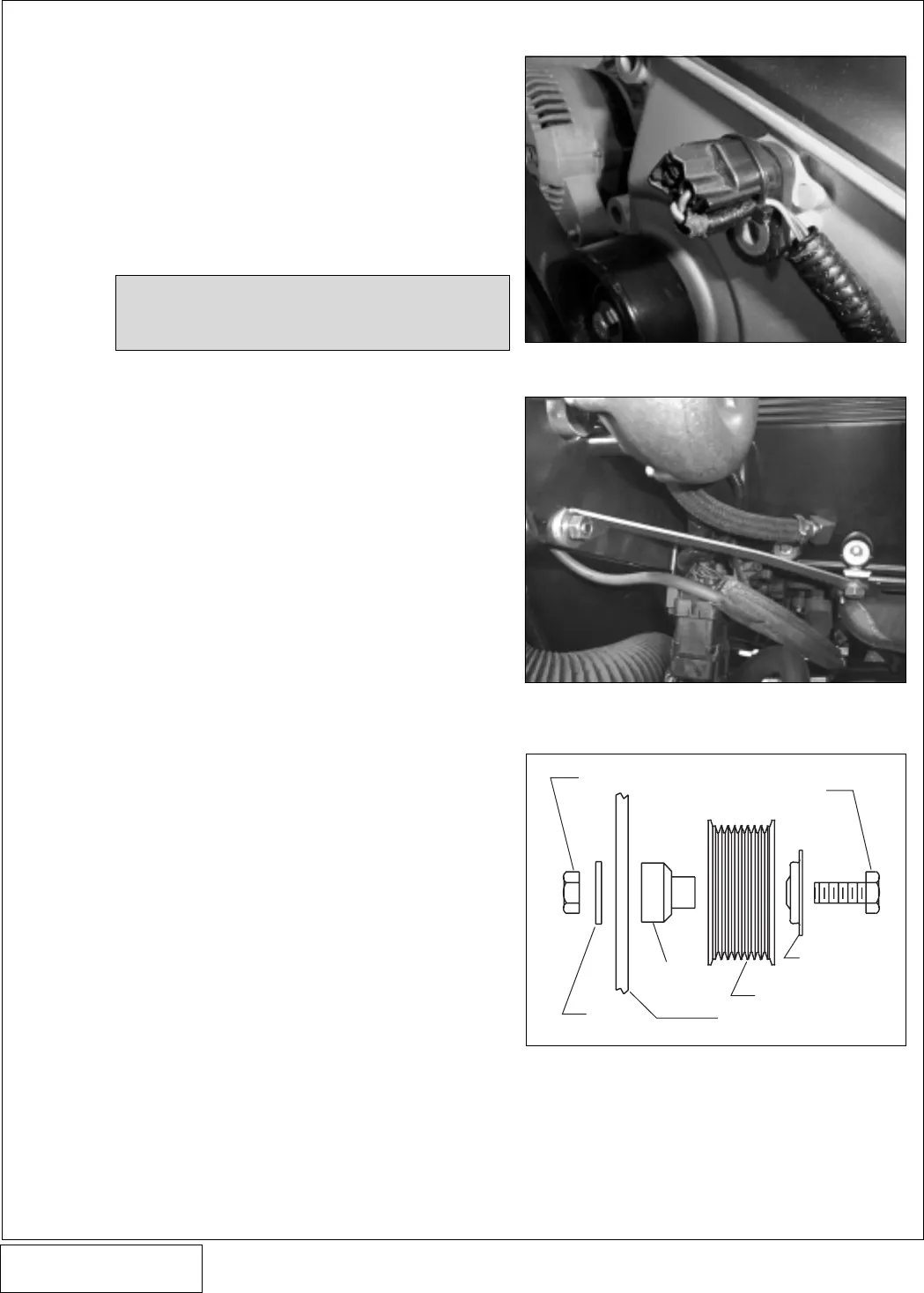
F. Bolt the grooved idler with dust cover and idler
spacer to the support plate using the 7/16-14 x
2.5" hex head screw, 7/16" nylock nut and
washer. Do not over tighten. (See
Fig. 10-c or
Fig. A-3 in the Appendix
.)
G. Mount the spring tensioner spacer to the mount-
ing bracket using the 1/4" hardware. Note the
orientation or position of the mounting holes of
the spacer (screws thread through the bracket
and into the spacer from the rear). Secure the
spring tensioner to the spacer/mounting plate
using the 3/8-16 x 4" bolt, 3/8" nylock nut and
washers. (See
Fig. A-3 in the appendix
.)
H. Attach the oil drain line to the supercharger and
secure with one #8 hose clamp. Hold the super-
charger into position on the mounting plate and
determine the correct oil drain line length and
trim. Ensure that there are no kinks, sharp
bends or upward travel in the drain line.
I. Mount the supercharger to the mounting bracket
and support plate using five 3/8-16 x 1.75"
screws, 3/8" washers and three M12 screws
and M12 washers. Connect the oil drain line
coming from the supercharger to the fitting on
the valve cover and secure with the other #8
hose clamp.
10
Fig. 10-a
Fig. 10-b
Fig. 10-c
Grooved Idler Assembly (Side View)
7/16” NYLOCK NUT
7/16”
WASHER
IDLER
SPACER
SUPPORT PLATE
GROOVED IDLER
DUST COVER
7/16-14 x 2.5”
HEX HEAD
SCREW
NOTE: There are two threaded holes. Attach
the bracket to the one closest to the
firewall.


