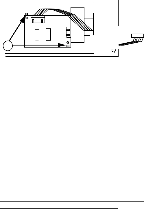
6. Note the position of the PCB assembly. Then remove
it by gently prying back the two retaining tabs (Figure
7, #1).
FIGURE 7
To replace the PCB and housing assemblies:
1. Position the PCB assembly and snap it under the two
retaining tabs (Figure 7, #1).
2.
Position the plastic spring plate and the attached
pieces so that the tabs line up (Figure 5, #1). Snap
the plate into position and hold it there.
3.
Insert the pointed end of the spring plate shaft through
the housing, and attach the e-ring (Figure 5, #3).
4.
Position the metal spring plate and snap it into place
over the tabs (Figure 5, #1).
5.
Connect the spring (Figure 5, #2) that holds the paper
stopper in place.
6.
Replace the frame assembly and connect the paper
tray assembly and the housing assembly.
ImageWriter II rev. Aug 87 SheetFeeder / 6. 11