3.
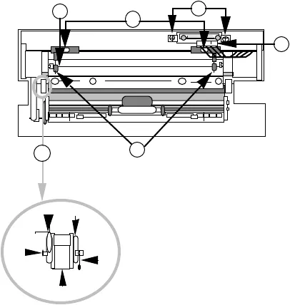
Line up the plastic hinges on both sides. Slide them
into position. (Figure 2, #1 shows the left side.)
4.
Use a pair of long, thin needlenose pliers to replace
the pivot shaft (Figure 2, #1) on the left
side. Slide the pivot pin onto the shaft (Figure 2, #1).
Repeat this step for the right side.
5.
Replace the paper guide (Figure 2, #2).
6.
Replace the paper guide springs (Figure 2, #3).
7.
Position the rear housing and the metal clamps
(Figure 2, #4), and replace the two screws.
Be sure the connector cable is in position.
8.
Position the connector plate with the two springs
underneath, and replace the two screws
(Figure 2, #5).
9.
Plug in the connector (Figure 2, #6).
10.
Replace the customer's two plasticized wire paper
-
support rods by sliding them into their holes on the
SheetFeeder housing and on the paper tray
assembly. (For correct orientation of the rods, refer to
the SheetFeeder Illustrated Parts List.)