042-288-B0-001, Rev. A2
93
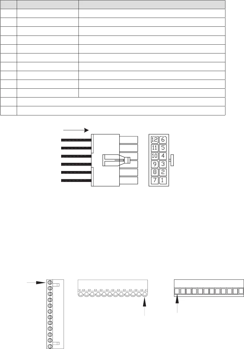
Fig. 8-9, APU Control Interface
8.10 ECM Alarm Interface
Terminal 1
Top View
Plug-side View
Wire-insertion-side View
Terminal 1
Terminal 1
Fig. 8-10, ECM Connector Arrangement
Pin Description Function
1 +12V Ignition Battery Ignition Battery Fused 12V from APU
2 Neg. Ignition Battery Ignition Battery Negative from APU
3 Low Oil Pressure Active LOW signal denotes low oil pressure.
4 Over-temp Active LOW signal indicates Over-temp.
5 Start Command Active LOW from ECM activates APU Start relay.
6 Common (Start – Stop) Common return between START and STOP relays.
7 Stop Command Active LOW from ECM activates APU Stop relay.
8 Over-speed Active LOW signal denotes engine RPM was exceeded.
9 Over-crank Active LOW signal denotes Over-crank Limit is reached.
10 Engine Run Active LOW signal denotes the engine is running.
11 Not Used
12 Not Used
8.0 Interconnection, continued
8.9 ECM APU Control Interface
The interface control is a 12-pin (2x6 row) Mini Mate-’N’-Lok style connector.


