042-288-B0-001, Rev. A2
91
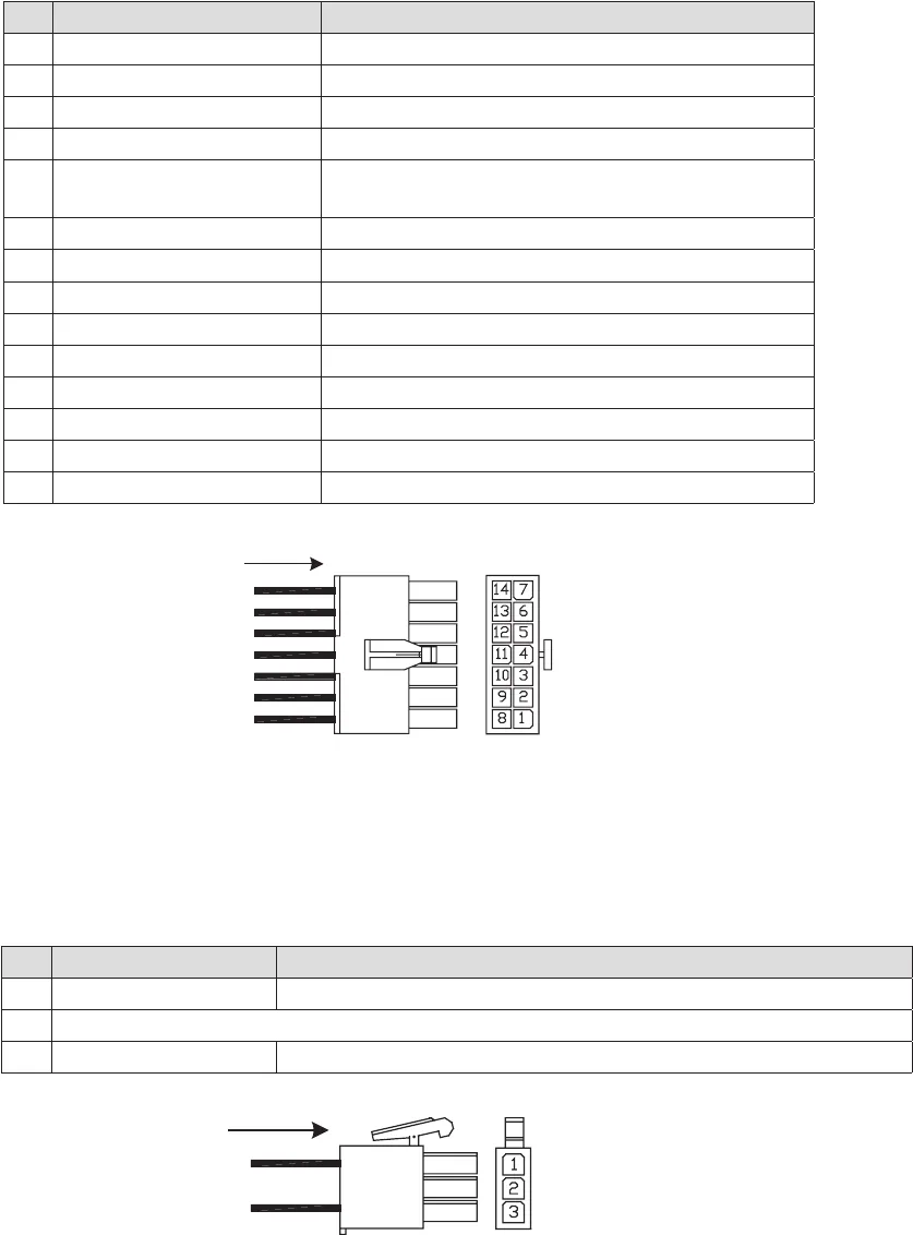
Fig. 8-5, ECM Enclosure Alarm Interface Connector
8.6 Inverter Battery DC Sense Interface Connector
ECM - Inverter Battery DC Sense Interface Connector J8. The interface control is a 3-pin (1x3
row) Mini Mate-’N’-Lok style connector.
Fig. 8-6, Inverter Battery DC Sense Interface Connector
Pin Description Function
1 Water Intrusion Sensor Contact OPEN (HIGH signal) denotes water
2 Water Intrusion Common Return signal path for sensor
3 Pad Shear Sensor Contact CLOSED (LOW signal) denotes pad shear
4 Pad Shear Common Return signal path for sensor
5 Low Fuel Pressure Sensor Contact CLOSED (LOW signal) denotes low fuel
pressure (LP versions only)
6 Low Fuel Pressure Common Return signal path for sensor
7 Gas Hazard Sensor Switch Active OPEN signal denotes gas hazard (Logic HIGH)
8 Gas Hazard Power/Alarm Return signal path for sensor (Common)
9 Gas Hazard Logic Power Logic power for Logic PCB & sensor (+12Vdc Fused)
10 Door Open Sensor Contact CLOSED (LOW signal) denotes door is open
11 Door Open Common Return signal path for sensor
12 No Connection
13 +12V Fused Fan
14 Common Fan
8.0 Interconnection, continued
8.5 ECM Enclosure Alarm Interface Connector
The Alarm Interface Connector (J10) is connected to the Power PCBA. The interface control
is a 14-pin (2x7 row) Universal Mini Mate-’N’-Lok style male connector.
Pin Description Function
1 DC Bus Sense (POS.) Output inverter battery bus – positive connection, 48 and 98Vdc buses
2 No Connection
3 DC Bus Sense ( NEG.) Output inverter battery bus – positive connection, 48 and 96Vdc buses


