90
042-288-B0-001, Rev. A2
Fig. 8-3, Gas Solenoid Interface Connector
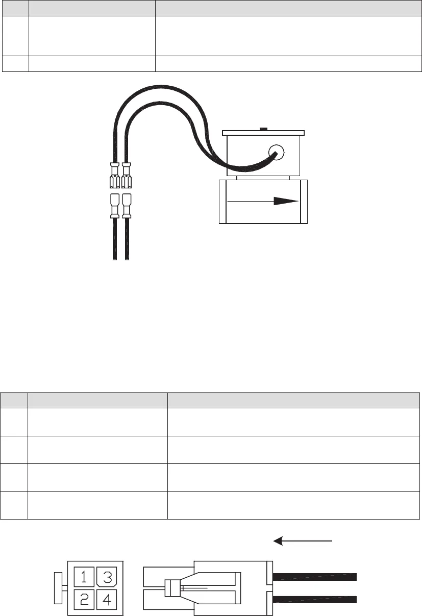
Fig. 8-4, Charger Control Interface Connector
8.4 Charger Module Control Interface Connector
The Charger Module – Control Interface Connector is connected between the
charger module and ECM with Sense/Power leads connected to the APU output DC bus. The
interface control is a 4-pin (2x2 row) Universal Mini Mate-’N’-Lok style male connector.
8.0 Interconnection, continued
8.3 Gas Solenoid Interface Connector
Pin Description Function
1 ECM Charger Control
(+) Yellow Wire
Connects pins 1 and 2 together, turning the charger
ON, i.e. Closed (LOW signal).
2 Inverter Battery
(+) Red Wire
Input power to charger module, operates on 48Vdc
battery pack to charge ignition battery.
3 ECM Charger Control
Orange Wire
ECM turns charger ON by applying a LOW signal to
this pin (referenced to ignition battery negative).
4 Inverter Battery (-)
Black Wire
NEGATIVE input power to charger module, operates
on 48Vdc battery pack to charge ignition battery.
Pin Description Function
1 Gas Solenoid +12V +12Vdc supplied to gas solenoid only when APU is ON
(running). APU Shuts OFF gas supply to cabinet during
any fail safe or fault condition.
2 Gas Solenoid Common Return path for gas solenoid.


