16
905077 REV B 7/23/14, 1970-78 CAMARO WITH A/C EVAP KIT PG 16 OF 28
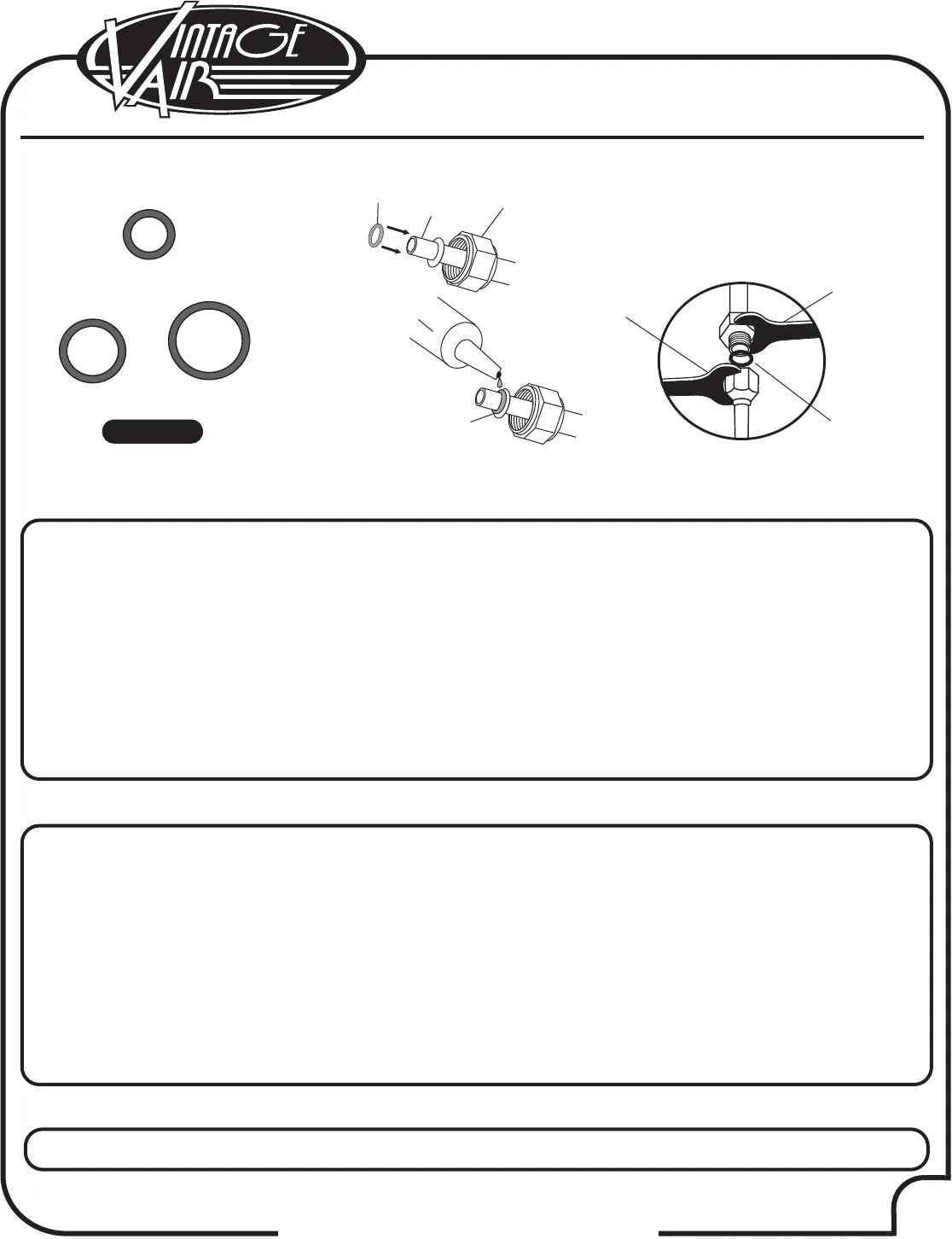
Twist With
This
Wrench
Hold With
This
Wrench
1. Refer to separate instructions included with modified hose kit.
For a proper seal of fittings:
Install supplied O-rings as shown
and lubricate with supplied oil.
Female
Nut
Male
Insert
Supplied Oil
for O-rings
#6 O-ring
#8 O-ring
#10 O-ring
Figure 19
O-ring,
Slide Over
Male Insert to
Swaged Lip
O-ring
O-ring
Lubricating O-rings
1974-78 Camaro Standard Hose Kit
Modified A/C Hose Kit
1. Locate the #8 compressor A/C hose. Lubricate (2) #8 O-rings (See Figure 19, above) and connect the 90° female
fitting w/ R134a service port to the #8 discharge port on the compressor. Route the 45° female fitting to the #8
condenser hardline coming through the core support (See Figure 21, Page 18). Tighten each fitting connection
as shown in Figure 19, above.
2. Locate the #10 compressor A/C hose. Lubricate (2) #10 O-rings
(See Figure 19, above) and connect the #10 135°
female fitting w/ R134a service port to the #10 suction port on the compressor. Route the 90° female fitting to the
#10 evaporator (See Figure 15a, Page 13, and Figure 21, Page 18). Tighten each fitting connection as shown in
Figure 19, above.
3. Locate the #6 evaporator A/C hose. Lubricate (2) #6 O-rings (See Figure 19, above) and connect the 90° female
fitting to the #6 hardline coming through the core support from the drier. Route the 90° female fitting
to the #6
evaporator (See Figure 15a, Page 13, and Figure 21, Page 18). Tighten each fitting connection as shown in
Figure 19, above.
1970-73 Camaro Standard Hose Kit
1. Locate the #8 compressor A/C hose. Lubricate (2) #8 O-rings (See Figure 19, above) and connect the 90° female
fitting w/ R134a service port to the #8 discharge port on the compressor. Route the 45° female fitting to the #8
condenser hardline coming through the core support (See Figure 20, Page 17). Tighten each fitting connection
as shown in Figure 19, above.
2. Locate the #10 compressor A/C hose. Lubricate (2) #10 O-rings
(See Figure 19, above) and connect the #10 135°
female fitting w/ R134a service port to the #10 suction port on the compressor. Route the 90° female fitting to the
#10 evaporator (See Figure 15a, Page 13, and Figure 20, Page 17). Tighten each fitting connection as shown in
Figure 19, above.
3. Locate the #6 evaporator A/C hose. Lubricate (2) #6 O-rings (See Figure 19, above) and connect the 45° female
fitting to the #6 hardline coming through the core support from the drier. Route the 90° female fitting
to the #6
evaporator (See Figure 15a, Page 13, and Figure 20, Page 17). Tighten each fitting connection as shown in
Figure 19, above.


