32
AVANTI Service Lift for Wind Turbines
2. Install the rest of the ladder sections from top to
bottom (see Fig. 2).
3. Install the rest platforms approximately every 9 m
(see Fig. 3 and installation drawing).
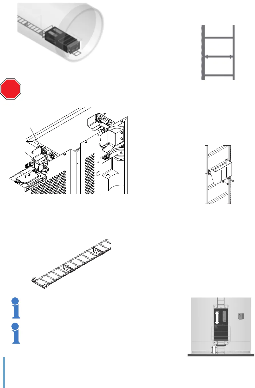
4. Position the cabin inside the bottom tower section
ensuring that bottom guiding rollers are aligned with a
ladder support (see Fig. 6).
5. Install the bottom mechanical stop and the bottom
safety position plate (see Fig. 8 and installation
drawing).
9.4 Assembly on site
After the tower sections are erected:
1. Climb up to the second tower flange.
2. While descending to the previous tower flange,
loosen connection bolts between the ladder rack
anchorages from the tower support brackets.
3. Lower down the loose ladder section until it
contacts the previous ladder section, so that no gap
exists.
4. Tighten the connection bolts between the ladder
sections (see Fig. 9).
5. Using two calibrated rods of Ø 12 mm check that
distance between ladder sections dents is 49.7 ± 0.5
mm.
6. While climbing up, tighten the M12 connection
bolts between the ladder rack anchorages and tower
support brackets with a torque of 12 N·m (see Fig.10).
7. Climb up to next tower flange and repeat actions 2
to 5 until there are no gaps between the ladder
sections.
8. Check that gap between anti-derailment bracket
and ladder stile is 4 mm.
9. With the service lift on bottom platform, adjust the
bottom mechanical stop so that it is possible to open
the double door just above the fence railing. The
service lift must stop before the cabin main structure
hits the bottom mechanical stop (see Fig. 11).
Fig. 6
Fig. 9
Fig. 10
Fig. 11
Fig. 8
Fig. 7
It is also possible to install the cabin and
bottom mechanical stop on site.
Mount the guiding rollers shafts into the
correct holes: green shafts into green
labelled holes and orange shafts into orange
labelled holes.
Service lift can be used during installation.
GREEN LABEL
AND SHAFT
ORANGE
LABEL
AND
SHAFT
STOP


