2. Remove air cleaner assembly and EFI induction
module assembly. Safely drain fuel from the fuel
lines and EFI induction module assembly. Refer to
appropriate Harley-Davidson
®
service manual.
3. Remove components from stock induction assembly
for re-use. Some components from the old system
are required for the new system. The Intake Air
Temperature (IAT) sensor and mounting screws,
Manifold Absolute Pressure (MAP) sensor, and
mounting screws, and the Idle Air Control motor.
See Pictures 6 and 7.
B. Assemble S&S
®
VFI Fuel Rail and Manifolds
Gasoline in EFI systems is pressurized. Failure to
carefully follow fuel rail preparation and assembly
instructions may result in personal injury
and/or property damage.
NOTES:
●
●
The included O-ring kit 55-5020, contains O-rings and
snap-rings that are not required for the Delphi
®
system
installation.
●
●
An additional Four (4) spare injector O-rings are included
in the O-ring package.
3
Picture 1
Stamped Number
Engine Type &
Cylinder Length
Manifold for Number Stamped Manifold for Number Stamped
Displacement Stock H-D
®
Heads On Manifold S&S heads On Manifold
S&S SSW+
111" 4.764" -- -- 16-5062 5062-398
117" 4.888" -- -- 16-5063 5063-408
124" 5.013" -- -- 16-5064 5064-417
Harley-Davidson
®
Twin Cam 88
®
88", 95", 106" 4.937" 16-5055 5055-410 16-5059 5059-410
100" 4.850" 16-5054 5054-405 16-5058 5058-405
107" 4.975" 16-5056 5056-415 16-5060 5060-415
116" 5.160" 16-5057 5057-429 16-5061 5061-429
124" 5.013" -- 16-5064 5064-417
Evolution
®
80", 89", 96" 5.550" 16-5055 5055-410 16-5059 5059-410
Special Order Specify 16-5027 -- 16-5065
Chart 1 S&S VFI Manifold Application and Identification
NOTE: SSW+ and Twin Cam 88
®
crankcases have 6.000" cylinder deck height. Evolution
®
big twin crankcases have 5.375" cylinder deck height.
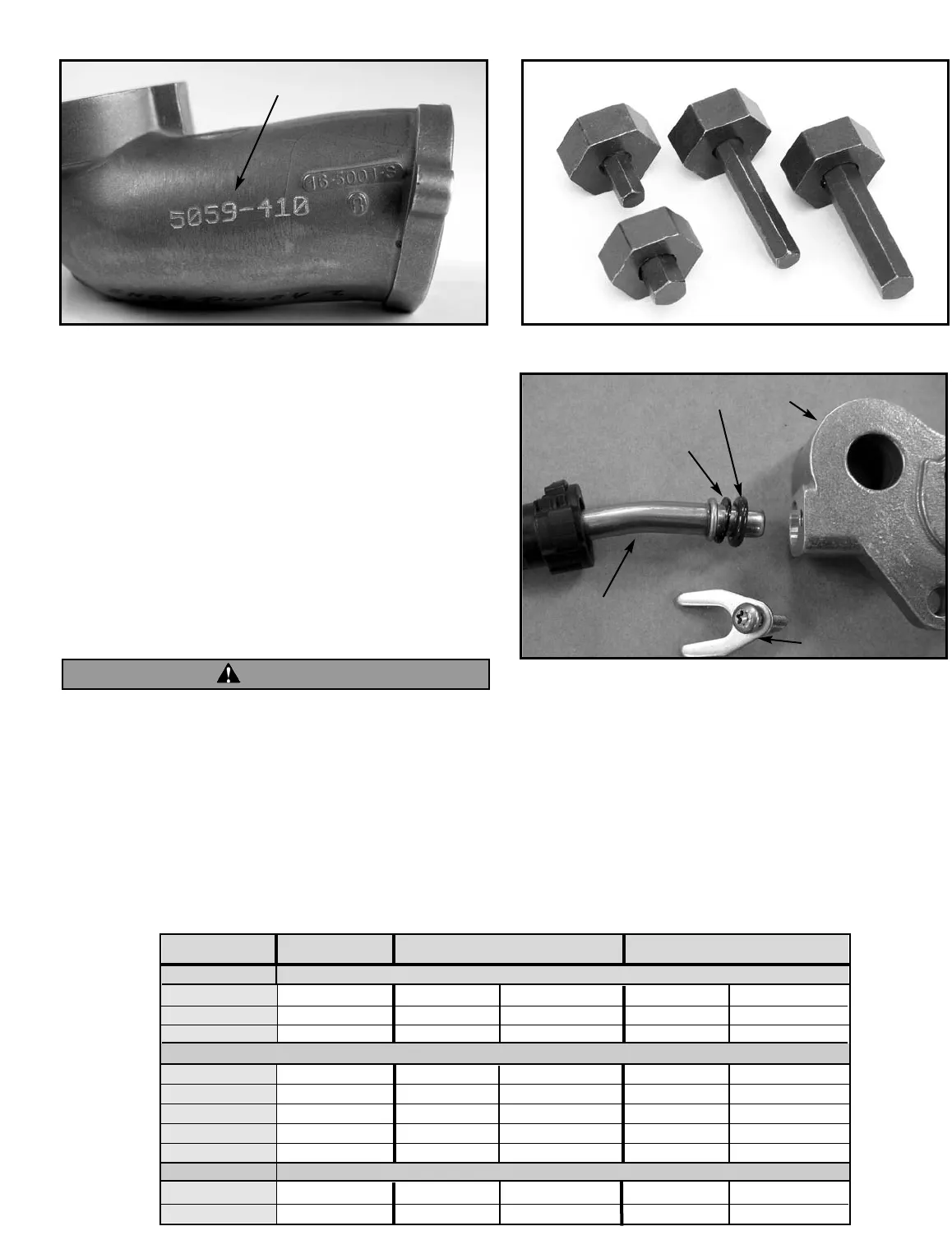
Picture 2
53-0040
Picture 3
O-Ring
Plastic Back-up Washer
OEM Fuel Line
Retaining Clip
S&S VFI Fuel Rail
WARNING


