Shure UC2 Hand-Held UHF Transmitter
Alignment2125C1044 (TK)
6. Connect the UC2 rf output test cable BNC end to the input port
(R) of the Zad-1 mixer.
7. Connect the rf signal generator, and set the frequency to the
operating frequency (from Table 2) minus 10.7 MHz.
8. Turn ON the UC2 and adjust R320 until the audio voltmeter
connected to the unbalanced output of the UC4 reads the same
as the deviation reference voltage, measured above, ± 0.1 dB,
or ± 0.2 dB for JA, JB frequencies..
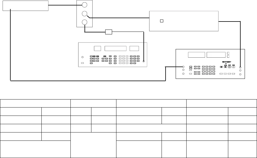
RF SIGNAL GENERATOR
AUDIO ANALYZER
DC BLOCK
NOTE: DC VOLTAGES ARE
PRESENT AT MOST RF TEST
POINTS. USE A DC BLOCK
ON THE RF SIGNAL GENERATOR
TO PROTECT TEST EQUIPMENT.
TRANSMITTER
ANTENNA
OUTPUT
R
I
L
ZAD–1 MIXER
MODIFIED SC4 IF RECEIVER
ANTENNA INPUT B
AUDIO OUT
TONE KEY SWITCH: ON
AUDIO
IN
SC4 IF Receiver UC2 Transmitter Audio Analyzer Rf Signal Generator
Output: Unbalanced Power: + 9 Vdc Measurement: AC level INT: FM
Gain: Maximum Gain: Minimum Output: 1 kHz INT: 1 kHz
Squelch: Mid Filters: Output amplitude: + 7 dBm
Tone Key switch: ON Low-Pass (30 kHz): ON Deviation: See Table 2
High-Pass (400 Hz): ON Frequency: Oper. Freq.
minus 10.7
MHz
Figure 13. Deviation Adjustment Voltage Test Set-Up,
Using a Modified SC4 IF Receiver


