Shure UC2 Hand-Held UHF Transmitter
20
Service Procedures
25C1044 (TK)
Adjustment Voltage
1. Disconnect the rf signal generator from the SC4 IF receiver.
2. Set the SC4 tone key switch on the SC4 front panel to ON.
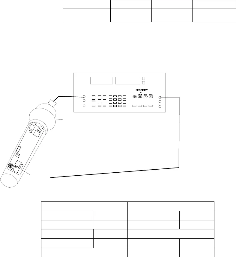
3. Connect the audio analyzer output to the MIC input of the
transmitter, using the test head or clip leads to the gold spring
contacts.
4. Turn the UC2 power back ON.
5. Adjust the audio analyzer output level (typically = –2.2 dBu) to
measure the following at TPA4 (U201, pin 7) :
UA, UB MB, MC, MD JA, JB KK
–6.8 dBu ± 0.2 dB
(354 mV ± 1 mV)
– 16.3 dBu
(118 mV ± 1 mV)
– 23.47 dBu
(52 mV ± 1 mV)
– 15.3 dBu
(133 mV ± 1 mV)
See Figure 14 for equipment set-up and equipment settings
for the rest of this test.
AUDIO ANALYZER
TEST HEAD
AUDIO
SIDE 1
TPA4
(U201, PIN 7)
UC2 Transmitter Audio Analyzer
Power: +9 Vdc Measurement: AC level
Gain: Minimum Frequency Output: 1 kHz
Group switch: See Table 2 Filters:
Channel switch: See Table 2 Low-Pass (30 kHz): ON
High-Pass (400 Hz): ON
Figure 12. Deviation Adjustment Voltage Test Set-Up,
Using a Modified SC4 IF Receiver


