Shure UC2 Hand-Held UHF Transmitter
14
Service Procedures
25C1044 (TK)
Alignment
Frequency
Use this service procedure to correctly align the transmitter’s
operating (output) frequency. C510 tunes the voltage-controlled
oscillator (VCO) to the operating frequency selected, with a 1 – 4 Vdc
tuning range.
C314 adjusts the reference oscillator on the synthesizer, U304.
FREQUENCY COUNTER
AUDIO ANALYZER
CH 2
CH 1
TP30
C510
U501
C314
J2*
RF
GND
S302
RED
S301
GREEN
TPRF1
*R40 and J2 are placed for JA, JB frequencies only.
RF GND: FEED THRU
HOLE ON PCB
R40*
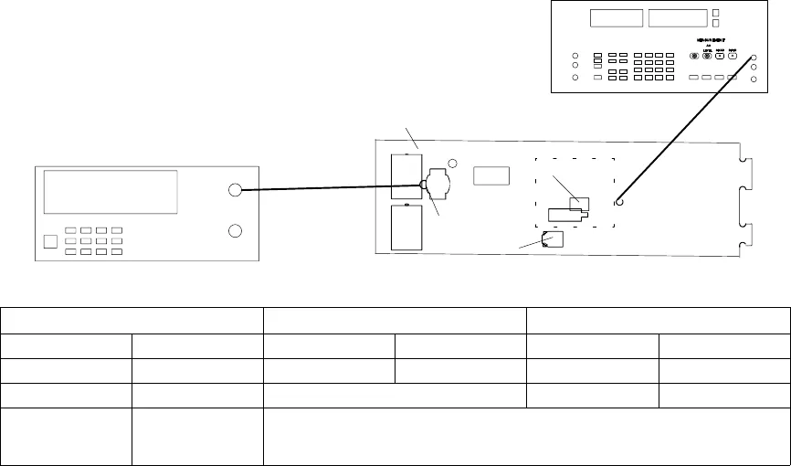
UC2 Transmitter Frequency Counter
Audio Analyzer
Power: ON (+9 Vdc) Operating freq: See Table 2 Connect + : TP30
Operating freq: See Table 2 Connect CH 2: TPRF1 and GND Connect – : RF GND
Channel switch: See Table 2 Measurement: DC level
Group switch: See Table 2 For Japan models with PCB versions:
“N” and earlier connect to J2
(pcb rf side 1)
Figure 6. UC2 Frequency Test Set-Up
1. Put a dc voltmeter across TP30 (tuning voltage line) and
RF GND.
2. Adjust the
VCO trimmer, C510, until the voltmeter reading
matches the appropriate entry in Table 2, ± 0.125 Vdc.
3. Adjust the variable capacitor, C314, until the frequency counter
measurement matches the appropriate frequency in Table 2,
± 1 kHz.
4. Leave the test cable connected to the rf output.
5. The dc voltmeter can be removed from TP30.


