Shure UC2 Hand-Held UHF Transmitter
Test Equipment Set-Up1125C1044 (TK)
Service Procedures
Measurement Reference
dBu is a measure of voltage, and dBm is a measure of power.
For example, the HP8903 should be labeled dBu instead of dBm
because it is a voltage measurement. These two terms are often used
interchangeably even though they have different meanings.
Audio levels in dBu are marked as dBm on the HP8903.
dB Conversion Chart
0 dBV = 2.2 dBu
0 dBu = 0 dBm, assuming the load = 600 Ω
Test Equipment
Most test equipment needed is described in the Shure Wireless
Service Equipment Manual. The following test equipment (or approved
equivalent) is also needed.
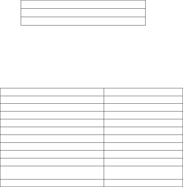
Table 1
Test Equipment
Equipment Type Model
Audio analyzer *Hewlett-Packard 8903B
Digital multimeter Fluke 87
Rf signal generator Hewlett-Packard 8656B
Frequency counter Hewlett-Packard 53181A
Spectrum analyzer (domestic) Hewlett-Packard 8590L
Spectrum analyzer (JA, JB) Hewlett-Packard 8591E
Shure UC4 receiver Shure UC4
Test head PT1840
Brass ring for use with test head PT1838–Y
BNC to “rocket launch” cable. For use on
Japan PCB versions “N” and earlier
95C8418
BNC(male) to unterminated 50W test cable
PT–1824
*Audio levels in dBu are marked as dBm on the HP8903B.
Test Equipment Set-Up
The alignment procedure is sequential and does not change,
unless specified.
1. Use the following test cables for all RF test points: Use PT1824
cable for European and USA models. For the Japan models use
the 95C8418 test cable for PCB versions “N” and earlier.
2. Keep the test cables as short as possible (less than 12 inches).
3. Include the insertion loss of the cables and connectors for all rf
measurements.
4. Dc voltages may be present at rf test points. As a precaution,
use dc blocks to protect the test equipment.


