VDSL Hospitality 100+ Rooms Setup Guide
1/05/05 Page 6 of 23
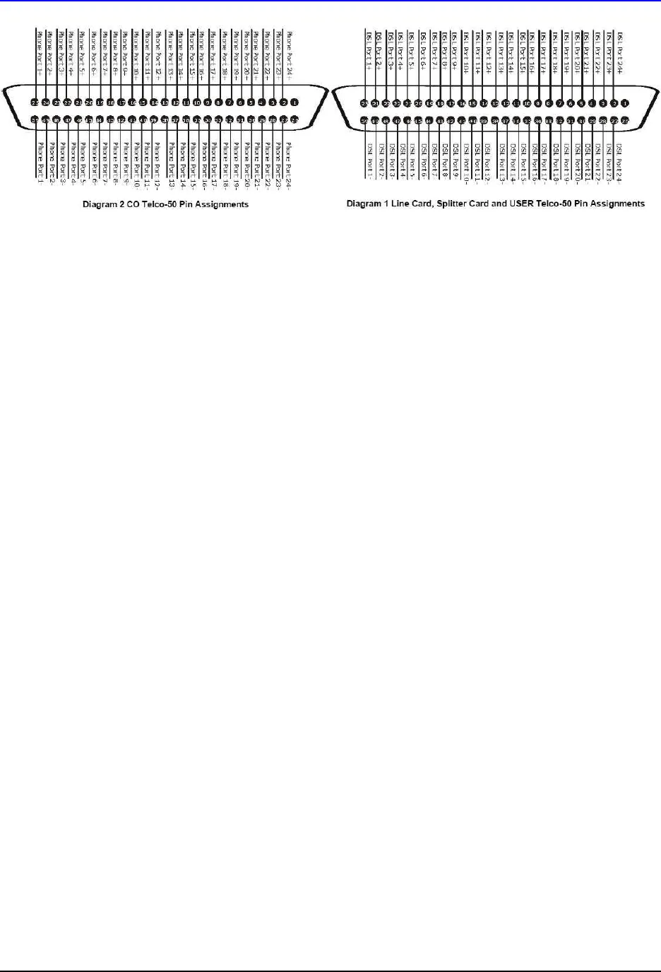
Pin-outs are located in the Appendix section of your unit’s User’s Guide. Please be sure to have the
contractor refer to these when installing your Telco-50 connectors; otherwise, your VES installation will
not work properly.
For more information on with connectors apply to the PBX and to room connections, please read the next
section.
Connecting everything together
Once you have the proper Telco-50 Connectors in place, and the Internet connection has been installed,
you should be ready to connect your equipment.
1. First you should connect your modem to your internet connection (cable, DSL, T1, T3, etc.) if the
ISP has not already done so. If you require assistance in doing this, contact your ISP for further
help.
2. Once the modem is installed, connect your VSG-1200 to the modem via Ethernet cable. From
the LAN ports of the VSG, you will need to connect your ES-3024 managed switch via another
Ethernet cable. You may also connect management and employee computers to the other LAN
ports on the VSG per your preference.
3. From the ES-3024, you will connect your VES-2500 line cards. Each line card will have its own
Uplink port, which will need to be connected to one of the ports on the ES-3024 via Ethernet
cables.
4. Next, you will need to connect the telephone lines to the VES-2500. The Telco-50 connectors for
the VES-2500 can be confusing. In order for a successful installation, you’ll need the VES-2500
main chassis and the VES-2500 splitter chassis. Each line card of the VES-2500 will support up
to 24 lines or users. You will also need a splitter card for each line card used. Line cards are
installed into the main chassis, and splitter cards are installed into the splitter chassis.
5. Once the line cards and splitter cards are installed into their chassis, you’re ready to connect your
Teclo-50 cables. First, connect the VDSL port on the line card to the VDSL port in the splitter
card via Telco-50 patch cables, which have a male Telco-50 connector on each end.
6. On the back of the splitter chassis there are two Telco-50 ports for each splitter card. The once
marked “CO” will be the incoming voice lines from the building’s PBX. The once marked “USER”
is the outbound port for the lines going to each room. Below is a basic diagram of you the voice
service is connected through the splitter chassis’s rear connectors.


