9.12.2 Eight-Reader Expansion Board (P/N: 03-10102-201E) - Jumper Selections
There are five jumper units located on the 8-Reader expansion PCB circuit board. The settings
are shown below.
• W1 at Pins 2 and 3 = PCB addressed to 30h (LO Address)
• W1 at Pins 1 and 2 = PCB addressed to 50h (HI Address = Default Settings)
• W2 and W3 at pins 1 and 2 = A/D is max 158 type
• W2 and W3 at pins 2 and 3 = A/D is max 7828 type
•
•
•
•
•
•
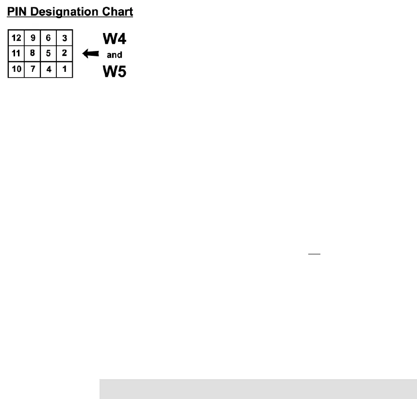
• W4 (for Readers e-h)
At pins 1 and 2, 4 and 5, 7 and 8, 10 and 11= Wiegand 5-Wire 5 volt card
readers
At pins 2 and 3, 4 and 5, 7 and 8, 10 and 11= Wiegand 5-Wire 12 volt card
readers
At pins 2 and 3, 5 and 6, 8 and 9, 11 and 12= PCSC 4-Wire 12 volt card
readers
• W5 (for Readers i-l)
At pins 1 and 2, 4 and 5, 7 and 8, 10 and 11= Wiegand 5-Wire 5 volt card
readers
At pins 2 and 3, 4 and 5, 7 and 8, 11 and 12= Wiegand 5-Wire 12 volt card
readers
At pins 2 and 3, 5 and 6, 8 and 9, 11 and 12= PCSC 4-Wire 12 volt card
readers
• W6 – Reader T/O
At pins 1 and 2 = 32 ms (PCSC Factory Set. Do not modify)
At pins 2 and 3 = 64 ms
• W7-W14 Reader Data Format
At pins 1 and 2 = Wiegand 5-wire (Data 1’s and Data 0’s) format
At pins 2 and 3= PCSC 4-wire (proprietary) format
• SW1 Switch Settings (to configure PCB for doors 5-12)
Switches 1, = OFF
Switches 2,3,4,5,6,7,8 = ON = 8 Reader PCB
Switch 5 = ON to enable Supervision Option of ALL Egress Sense Inputs
(#24, 26, 28, 30, 32, 34, 36 and 38).
Switch 5 = OFF to disable Supervision of ALL Egress Sense Sense Inputs
(#24, 26, 28, 30, 32, 34, 36 and 38).
NOTE Supervised Egress Option requires i4+07.010.02 series (or newer) IQ-
400 firmware.
IQ-400 Installation Manual Page 92 of 100 33-10057-001-A


