11
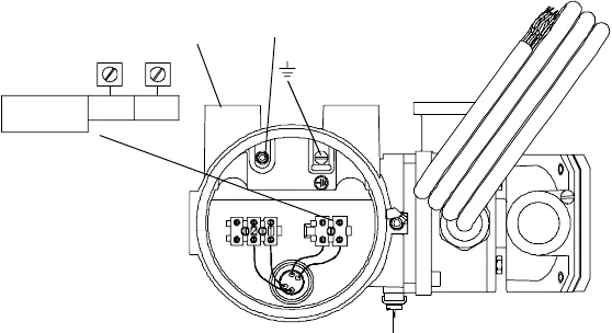
Figure 9. Power supply wiring for remote booster amplifier
Wiring from the remote booster amplifier to the sensor
The remote version of the booster amplifier requires connection of two
cables from the booster amplifier to the junction boxes on the sensor:
• 9-wire cable (signal wires) — This cable is supplied by Micro Motion,
and is pre-attached to the booster amplifier.
• 2-wire cable (drive wires) — In some locations, this cable may be
supplied by Micro Motion. If the cable is not supplied, use twisted-
pair 18 AWG (0,75 mm
2
) 2-wire cable.
To connect the 9-wire cable (signal wires):
1. Do not modify connections at the booster amplifier.
2. Do not place the 9-wire cable and 2-wire cable in the same cable tray.
3. At the sensor end of the 9-wire cable (see left side of Figure 10):
a. Clip all four drain wires and leave them disconnected.
b. Clip the red and brown wires and insulate them.
c. Matching by color, connect the remaining wires (except for the
orange wire) to the corresponding terminals from the sensor
feedthrough.
d. The orange wire in the cable does not have a corresponding
orange wire from the sensor. Connect the orange wire to the
terminal indicated in Figure 10.
e. Terminate the cable braid inside the cable gland.
Screw and
terminal cover
Internal
ground screw
L/L
1
N/L
2
85-250 VAC
50/60 Hz
External ground screw for use where local codes or authorities
permit or require such connections
Power supply
conduit opening


