13
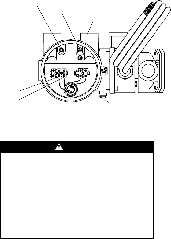
Figure 11. Remote booster amplifier – 2-wire cable (drive wires)
STEP 5. Wiring the sensor to the transmitter or direct host
WARNING
Failure to comply with requirements for intrinsic
safety in a hazardous area could result in an
explosion.
• For installation in an area that requires intrinsic safety,
refer to Micro Motion UL, CSA, or ATEX
documentation, shipped with the sensor or available
from the Micro Motion web site.
• For hazardous area installations in Europe, refer to
standard EN 60079-14 if national standards do not
apply.
Remove screw and terminal
cover before installing wiring.
Re-install cover before operating
Drive wiring
conduit opening
Internal ground
screw
Ter mi n a l 2
Ter mi n a l 1
External ground screw


