Refrigerant Vapor Transfer
A WARNING
If the required vacuum level cannot be reached due to
the presence of a large leak in the chiller, the vapor
recovery process should be stopped. The constant in
filtration of air into the chiller may contaminate the
refrigerant.
Refrigerant vapor recovery is required after the liquid re
frigerant has been removed. Most refrigerant vapor can be
recovered by evacuating the chiller or storage tank and con
densing the vapor. The United States EPA requires the evac
uation level for low pressure chillers to be 29 in. Hg
(25 mm Hg absolute). Refer to Table 5 for additional
information.
Before using the pump for vapor recovery, make sure it
is at the correct operating temperature of 120 F (49 C). This
can be achieved by running the pump on air only for ap
proximately 15 minutes. If the pump is operating below op
erating temperature with refrigerant, excessive amounts of
refrigerant will be absorbed into the oil, causing dilution of
the oil. This condition may cause reduced vacuum capabil
ity and may shorten the life of the pump.
NOTE: If oil dilution is affecting the pump’s ability to achieve
29 in. Hg (25 mm Hg absolute), an oil change may be re
quired. See the Maintenance section on page 15.
BEFORE TRANSFERRING REFRIGERANT VAPOR -
When transferring refrigerant vapor from a chiller to a stor
age tank, connect the 12-ft refrigerant hose from the vapor
valve on the chiller to the suction service valve on the pump.
See Fig. 11. Copper tubing is factory installed from the
pump to the oil separator. Connect a 6-ft refrigerant hose
from the discharge connection of the oil separator to the in
let of the tube-in-tube condenser. See Fig. 4 for location.
Connect another 6-ft refrigerant hose from the refrigerant
outlet of the tube-in-tube condenser to the vapor valve on
the storage tank. See Fig. 4. Close the bottom valve on the
chiller and turn off the pump. The tube-ln-tube condenser
must be evacuated before starting this process.
The tube-in-tube condenser must be evacuated. Make sure
all refrigerant hose valves are closed. Remove the refriger
ant hose end connected to the pump suction service valve.
Remove the refrigerant hose end connected to the top valve
on the storage tank and connect it to the pump suction serv
ice valve. Close the pump discharge service valve and re
move the 1/4-in. cap on top of the pump discharge service
valve. Open all valves between the suction and discharge
service valves of the pump. Turn on the pump for about
5 seconds to evacuate the tube-in-tube condenser. The air
will be discharged through the 1/4 in. discharge port on the
pump discharge service valve. Once the evacuation is com
plete, reconnect the refrigerant hoses to their original con
nections. Replace the 1/4-in. cap on the pump discharge
service valve. Open the pump discharge service valve.
Connect a water hose to the water inlet connection (lo
cated on the bottom of the tube-in-tube condenser) and the
other water hose to the water outlet connection (located on
top of the tube-in-tube condenser). A water flow rate of ap
proximately 2 gpm (.012 L/s) is required at 70 F (21 C).
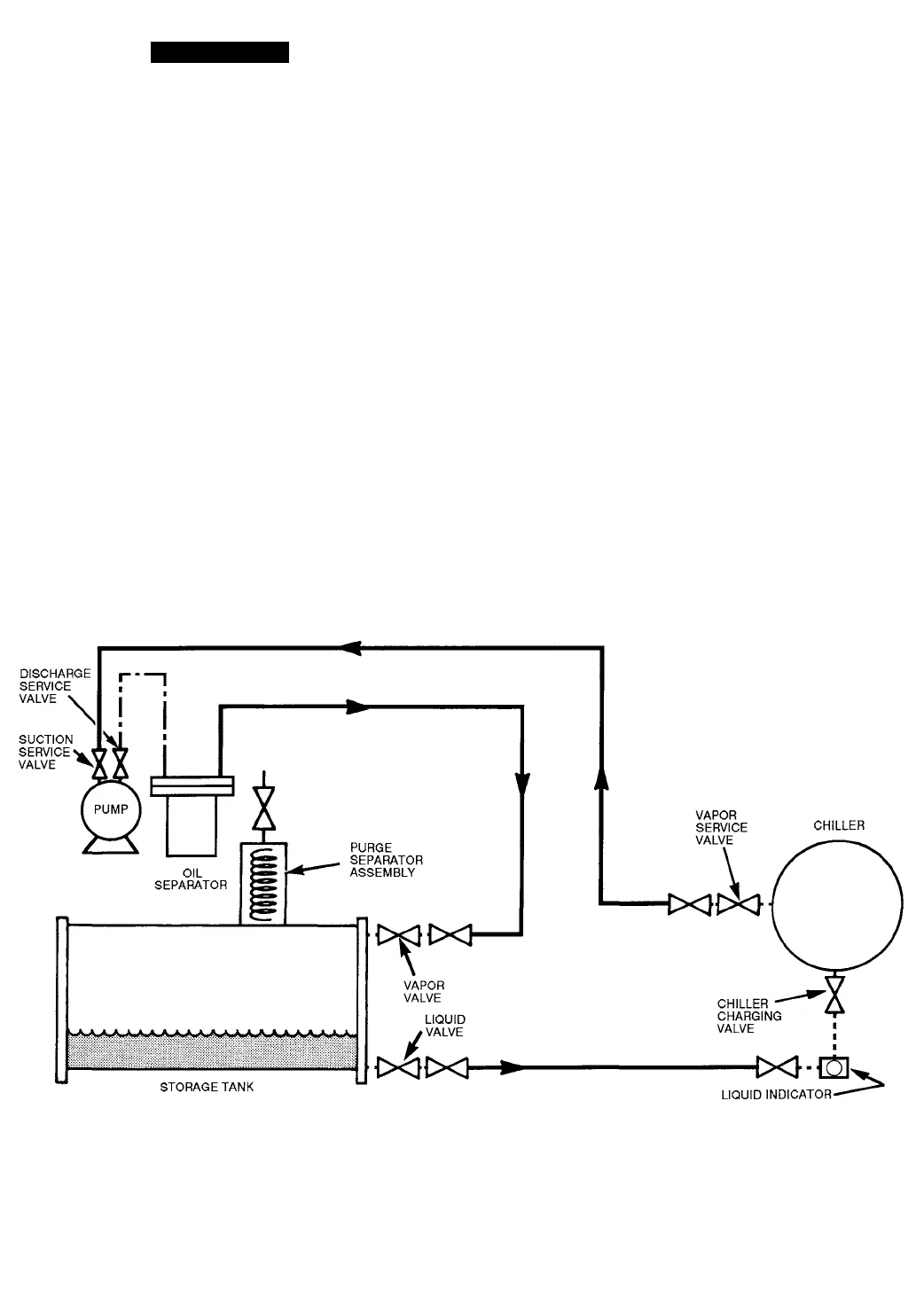
Refrigerant Hose
Direct Coupled Connection
Factory-Installed Copper Tubing
Fig. 10 — Liquid Refrigerant Transfer
(From Storage Tank to Chiller)
10


