— 7 —
ANTENNA CONNECTIONS
This receiver is designed for UHF/VHF reception. A 75 ohm
terminal is provided for UHF and VHF receptions. When
connecting a CATV antenna system, connect the 75 ohm
coaxial cable directly to the 75 ohm terminal. For 300 ohm VHF
antenna, use the adapter (included with the TV set).
CIRCUIT PROTECTION
Fuse F601 (4A) is included in the AC line. This fuse must be
replaced with the proper fuse. (See Parts List.)
FOR CONTINUED PROTECTION AGAINST A
RISK OF FIRE, REPLACE ONLY WITH THE
SAME TYPE 4A, 125V FUSE.
ATTENTION: POUR MAINTENIR LA
PROTECTION CONTRE LES RISQUES D’
INCENDIE UTILISER UN FUSIBLE DE
RECHANGE DE MEME TYPE 4A, 125V.
+B VOLTAGE CHECK
Connect voltmeter + lead to TJ1 130V and – lead to ground
(TE7). Connect receiver to AC 120V line. Tune receiver to an
active channel. Reset the picture controls to the FACTORY
PRESET levels (press remote control RESET key twice).
Voltage must measure between +128.0V and +132.0V. If the
voltage is out of this range, the power circuit must be checked.
No +B adjustment is provided on this chassis.
HORIZONTAL CENTERING ADJUSTMENT
1. Tune receiver to an active channel.
2. Check that picture is in the horizontal center of TV screen.
If picture is too right or left, perform steps 3 ~ 6.
3. Turn off the receiver and disconnect the AC power cord.
4. While pressing the MENU key, reconnect the AC power cord.
The Service Menu display will now appear.
5. Select No. 03 HP (Horizontal Phase) with ▲ or ▼ key.
6. Adjust the data with + or – key for horizontal center.
To turn off the Service Menu display, press the MENU key.
VERTICAL SIZE ADJUSTMENT
1. Tune receiver to an active channel.
2. Check the vertical size of the picture. If the vertical size is too
large or small, perform steps 3 ~ 6.
3. Turn off the receiver and disconnect the AC power cord.
4. While pressing the MENU key, reconnect the AC power cord.
The Service Menu display will now appear.
5. Select No. 04 VS (Vertical Size) with ▲ or ▼ key.
6. Adjust the data with + or –key for full scan. To turn off the
Service Menu display, press the MENU key.
VERTICAL CENTERING ADJUSTMENT
1. Tune receiver to an active channel.
2. Check that picture is in the vertical center of TV screen. If picture
center is too low, add a cutting wire to R513.
VCO ADJUSTMENT
Note: VCO must be adjusted after IC101 (Signal Processor),
IC802 (EEPROM) or T151 (IF VCO Coil) is replaced.
1. Tune receiver to an active channel.
2. Set the picture controls to the Sports level.
3. Connect digital voltmeter + lead to pin 58 of IC101(TP10)
and – lead to ground (TE 7).
4. Confirm a reading of 3.6 ±0.6 VDC.
5. If voltage is out of specifications adjust T151 for 3.6 ±0.6
VDC.
RF-AGC ADJUSTMENT
1. Tune receiver to strongest VHF station in your area.
2. Set contrast and brightness controls for maximum.
3. Turn off the receiver and disconnect the AC power cord
(120V AC line).
4. While pressing the MENU key, reconnect the AC power
cord. The Service Menu display will now appear.
5. Select No. 42 RAD (RF AGC Delay) with ▲ or ▼ key.
6. Adjust the data with + or – key in the direction which causes
snow to appear, then in the opposite direction until the snow
just disappears.
VIDEO LEVEL
1. Connect color-bar generator to antenna terminal.
2. Turn off the receiver and disconnect the AC power cord
(120V AC line).
3. Connect oscilloscope to TP16(Q202 emitter) and ground.
4. While pressing the MENU key, reconnect the AC power
cord. The Service Menu display will now appear.
5. Select No. 46 VL (Video Level) with ▲ or ▼ key.
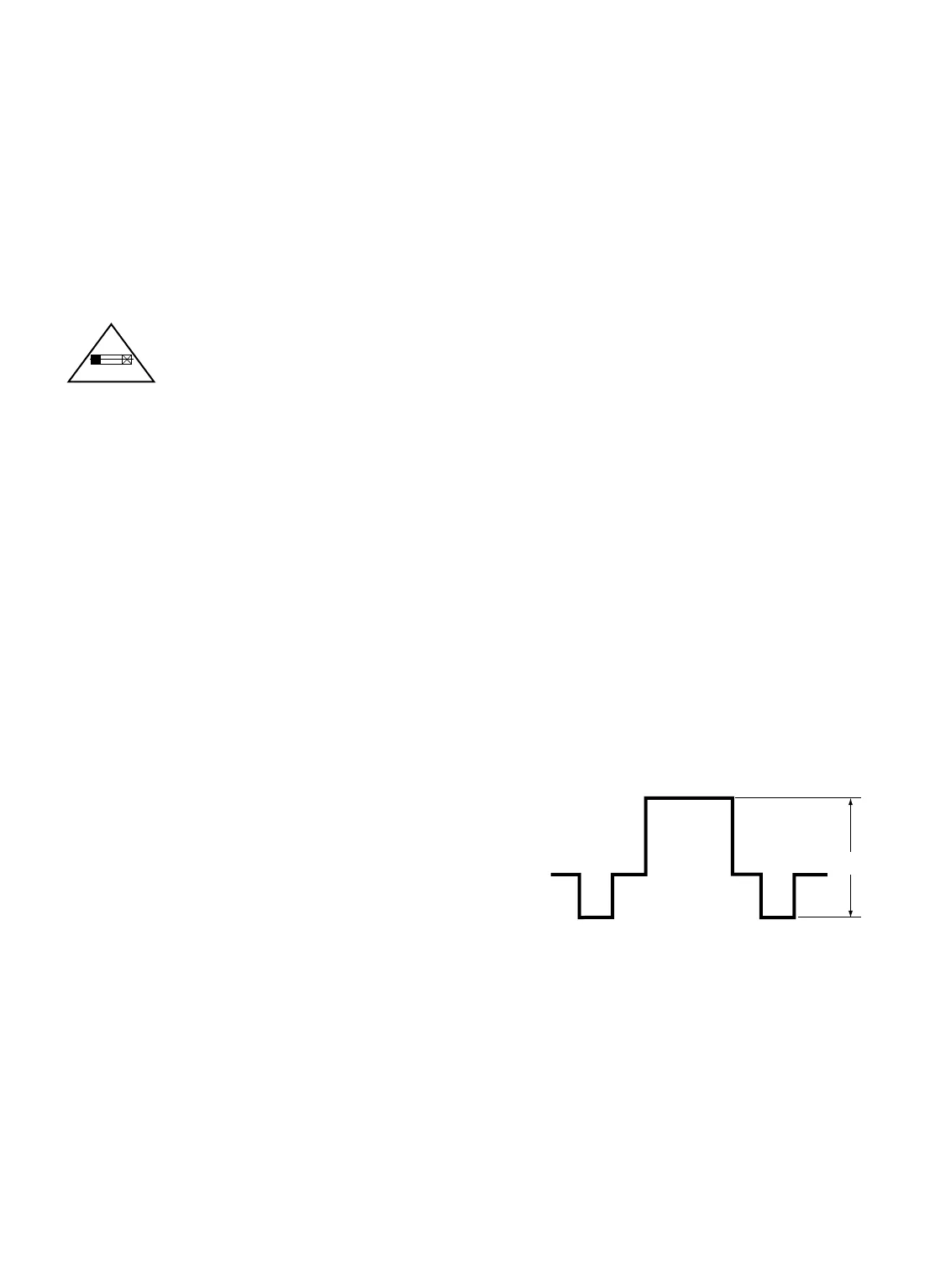
6. Adjust the + or – key for an oscilloscope reading of 1.0±0.1
Vp-p at TP16. Press the MENU key to turn off the Service
Menu display.
1.0 ±0.1 Vp-p
Figure 4.