Installation
I
I
n
n
s
s
t
t
a
a
l
l
l
l
a
a
t
t
i
i
o
o
n
n
Megapixel IP Camera can be connected in either 1 to
1 connection where one camera is connected to one
PC client or 1 to many connections where one camera
can be connected to several PCs.
Connection
Topology
Generally, LW9424 megapixel Network PTZ Camera
and PC is connected in 1-to-1 mode or 1-to many
configuration.
1:1 Connection .
R em ote C enter
(P C SW )
One camera is installed at a site where video images
are transmitted. A PC is installed at a central location
to receive and view the video images on an analog
monitor. Audio and serial data are transferred in either
direction.
1:N Connection .
In this configuration, a site can be monitored from
many remote central locations. Although up to 64 PCs
can be connected to one camera, in the real network
environment, network bandwidth can limit the
maximum connections.
In case that a PTZ is connected to more than 1 client,
to get stable images, the number of client is limited
for each Bitrate as below.
Multicast Mode
If the network supports multicasting, a large number
of PCs can be used to receive video effectively from a
camera using a single streaming of video and audio.
However, multicast mode is possible only when
network environment supports multicast.
Smart Station
Smart station is a Window-based remote monitoring
program in order to monitor or control video, audio,
and events in real time from several IP cameras. Please
refer to the Smart station User Manual for more in
detail.
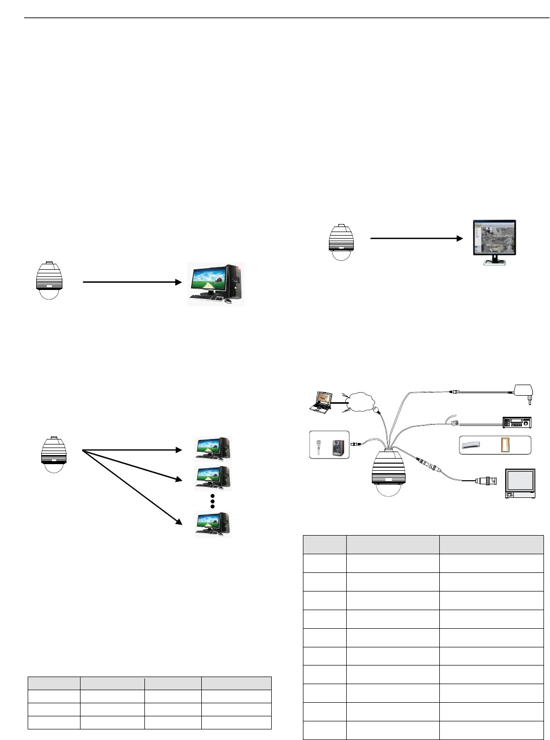
Basic Connection Overview
Browser
Power
MIC Speaker
INTERNE T
Controller / DVR
RS-485
LAN Cable
Audio
Cable
DC12V
IR
Sensor
Door
Switch
Sensor I/O
Monitor / DVR
BNC
Port Description of Alarm I/O Pin out


