UPDATED: 6/2014 Instruction Manual IM-268-11 2014© Bally Refrigerated Boxes, Inc. 5
A. When erecting a door panel for an installation on a concrete floor and without Bally
floor panels, it is necessary to provide a cutout in the concrete floor for all freezer
applications so that the heater channel may be inserted to prevent icing. Doors
intended for Coolers are simply set on top of the concrete.
•
If your door sticks out at the top, your frame is not plumb. Move the bottom of the
frame in or out to correct this problem.
•
If the gap at the top of the door is inconsistent, your frame is not level and the door
latch may not work properly. Shim the low side of the frame to level it with the high
side.
B. Caulk and seal any gaps under panels or door to floor. Apply base trim as per plan
view. For outdoor installation it is recommended that all exterior panel joints be
caulked during installation.
C. Anchor panels to floor using either Continuous Angle provided or, for outdoor boxes,
L-bracket attachments known as WA-1 or Wa-2. See Figure 8.
5. Assembly of With-Floor Walk-Ins
A. Make sure the floor is level. The entire area beneath the
Walk-In floor should be covered with a heavy polyethylene
va
por barrier to prevent possible damage by moisture.
(Check state and local codes to determine the mil
thickness.)
B. Check plan view for any special panel configuration, then
place a 23½” wide floor end panel along the most logical
starting point (usually the furthest corner from existing
building wall). Level the floor panel to high point of
concrete slab. See Figure 9.
C. Install the next panel and align. Level to the high point of
the concrete slab every time a new panel is installed.
D. Install shims (Bally recommends asphalt shingles) under
corners and cross panel joints as needed to ensure proper
support and levelness of panels. Be sure the shims are not
more than 23” apart at any given point under the panel.
Place additional shims, equally spaced, along the door
frame area for proper support, and to eliminate potential
sagging.
E. Continue to install floor panels as per Plan View, locking
each panel to its adjoining panel, and keeping ends of
panels even. Continue until all floor panels are assembled,
check for levelness and sqaureness. (Adjust if necessary.)
F. Check bottom section of door to be used to insure the
proper door is in the correct location. Doors are specifically
located by the floor plan drawing which is enclosed with
the installation instructions (A freezer door may have a
different stepplate condition than a cooler door Follow the
suffix 01 – 02 that corresponds to the drawing).
G. If structural steel is required it should be located and
installed before installing further.
6. Vertical Panel Installation
A. Determine the critical areas to find a starting point (For smaller
Walk-Ins this is the door location); this section must be perfectly
plumb and square to insure proper operation of the door.
B. Begin by erecting a vertical corner panel (If the Walk-In is being
installed near a building start at a corner nearest that). Speed-Lok
holes are always on the left when facing the interior of the panel.
C. Erect the vertical panels to the right and left of the corner panel
(Check the plan view), align tops of the panels and check for
plumb and level. Lock panels together, check to be sure the
proper metal finish is exposed where specified on the plan view.
D. When enough vertical panels have been set to allow installation
of the first ceiling panel, install the panel walls in an order that
will allow a ceiling section to be installed before proceeding with
more panel walls. Fasten ceiling panels to one another. When a
few are in place, lock the first ceiling panel to vertical panels.
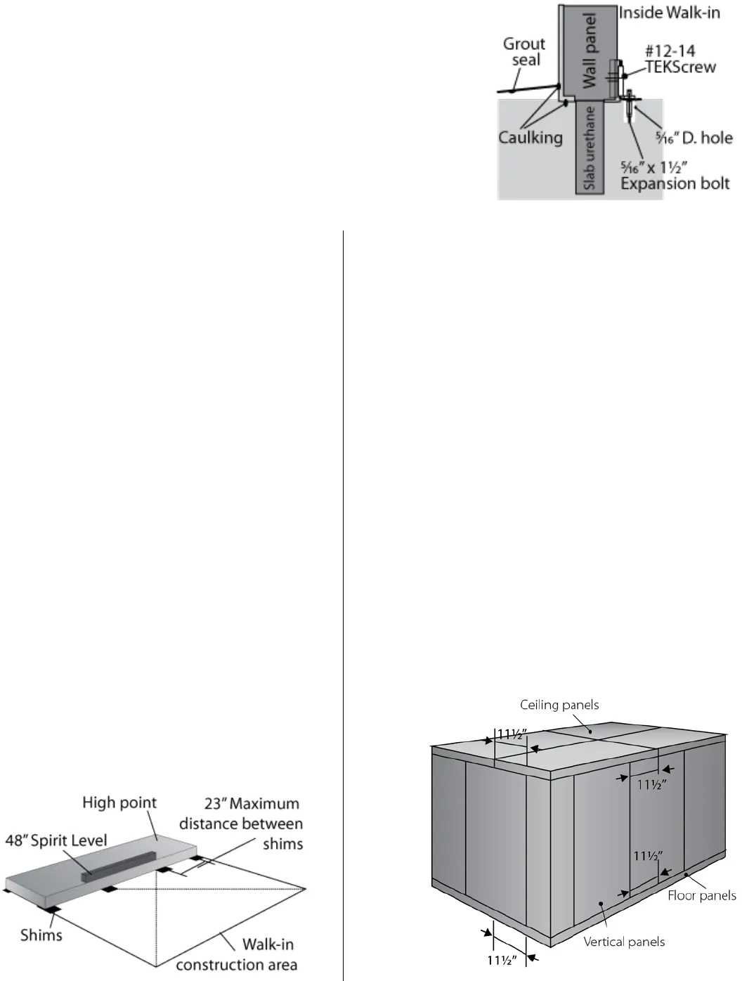
E. To check for correct alignment measure the distance from the
edge of the ceiling or floor to the nearest vertical joint. This
should be 11½” and maintained at every joint of the Walk-In. Use
a staggered locking sequence as shown in Figure 6. See Figure 10.
F. When all walls and ceiling panels are in place, lock all vertical
panels to floor panels. Door sections are held down through the
threshold plate. Drill through thresholds’ pre-drilled holes into
floor. Secure to floor with screws provided. See Figure 11.
G. For a Walk-In requiring anchors on the outside of the walls, begin
by centering anchors WA-3 to vertical panel joints and WA-4 to
corners. See Figure 12.


