PARTS LIST
For Figure 1 - Screw adjustment
control
S23-12327
CCW - “A” Mtg., CW - “B” Mtg.
S23-12328
CW - “A” Mtg., CCW - “B” Mtg.
be to the outside, and spools must freely slip into the bores.
9. Install spring (20) over the spool extension on one side only. See chart for location
relative to the 1/8” pipe plug.
10. Install plugs (17) with O-rings (16). Install remaining parts in plugs.
11. Place two spring washers (24), nested with the bent sections matching each other,
into the large hole in the servo link,
12. Place washer (19) against the spring washers.
13. Install O-ring into groove in the remaining shear seal (25). Note: This shear seal
does not contain the two .094” (2.4 mm) radius scallops in the face. Place on top of
washer (32). Position shear seal to match the lip on the servo link.
14. Install control on pump and torque bolts to 30 lbs-ft. (40.8 Nm).
8
Pump Shaft Control Spring loc.
Rotation mounting to 1/8” plug
clockwise A same
clockwise B opposite
c/clockwise A opposite
c/clockwise B same
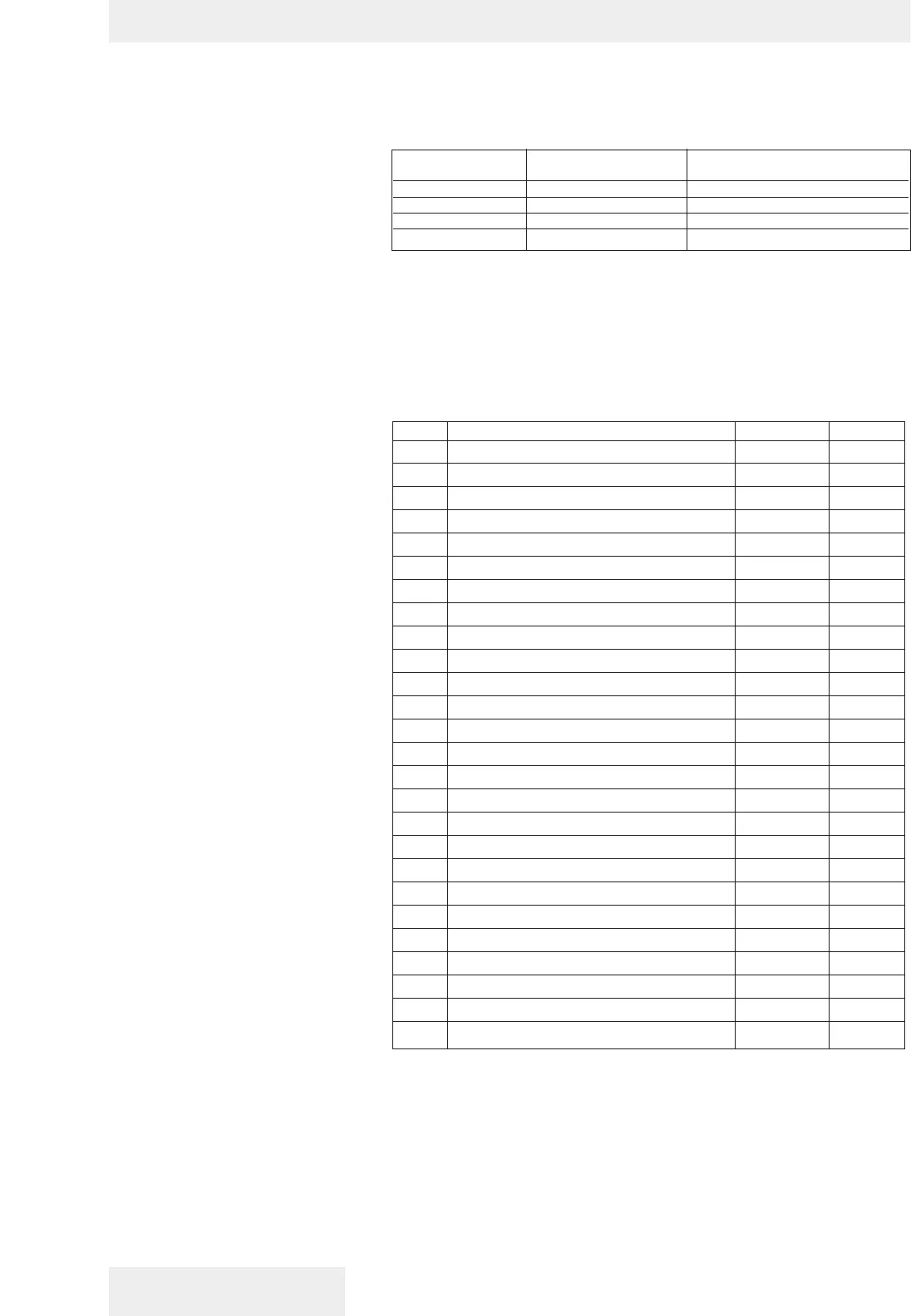
GOLDCUP CONTROLS SERIES 100
ITEM DESCRIPTION PART NO. QTY.
1 Servo shaft assy. S13-48438 1
2 Screw, hwhd. 3/8-16 x 1-1/4 353-25018 4
3 NOT USED
4 Ring, WT 5100-50 356-65070 1
5 O-ring, 70 S-1 ARP 013 671-00013 1
6 Washer, Nyltite #37-3/8” 631-45007 4
7 O-ring, 70 S-1 ARP 017 671-00017 2
8 Shear seal 033-71371 1
9 Thrust washer 350-10103 3
10 NOT USED
11 Control cover 033-54647 1
12 Hex flush plug, 1/8” pipe 431-90204 1
13 O-ring, 90 S-1 ARP 905 691-00905 3
14 Plug, 5P5N-S 488-35028 1
15 Spool 033-72180 2
16 O-ring, 90 S-1 ARP 906 691-00906 2
17 Plug 033-91889 2
18 Nut, cover 033-91890 2
19 Thrust washer 350-10064 1
20 Spring 033-72198 1
21 Soc. setscrew, 10-32 x 1 311-50002 2
22 Nut 333-67000 2
23 Spring pin 325-12120 2
24 Finger spring 350-10067 2
25 Shear seal 033-70525 1
26 Control cover gasket 033-91058 1