GOLDCUP CONTROLS SERIES 100
CODE 1 - SCREW
ADJUSTMENT CONTROL
S23-12327
“A” Mounting CCW Rotation
“B” Mounting CW Rotation
S23-12328
“A” Mounting CW Rotation
“B” Mounting CCW Rotation
DESCRIPTION
DISASSEMBLY
See Figure 1
REWORK OF WEAR PARTS
PREPARATION FOR ASSEMBLY
ASSEMBLY
The screw adjustment spring offsets the rotary servo to the maximum displacement as
adjusted by the screw. The operator needs only to override the spring offset torque of
approximately 20 lbs-in. (2.26 Nm) with the rotary servo stem to manually reduce dis-
placement. The minimum displacement is set by the adjustable screw which deter-
mines the minimum rotary servo command. The pressure compensator override is
independent of this control. A pump with this control acts as with a traditional pressure
compensator. In the absence of an overriding rotary servo command the pump is held
at the adjustable maximum displacement. The maximum screw is adjustable from
approximately 100% to 0%. The minimum screw is nominally set at zero stroke but is
adjustable from -50% to + 100% displacement.
1. Remove screws (2). Remove control from pump. Examine servo plate for exces-
sive scratching. Note if orifices in stem are open. If servo plate is scratched or orifices
appear to be plugged, remove plate and servo stem by removing two socket set
screws from plate, then alternately loosening the two button head screws under the set
screws.
2. Remove retaining ring (4) and press the shaft assembly through the valve body.
3. Examine shoes (8) and (25) for contamination in balance pads or excessive
scratching on faces. Note: the two shoes are not identical and must be installed in the
proper position on reassembly.
4. Remove the plug (17) with attached parts. Remove the spools (15) and spring
(20). Examine spools and bores for free motion, wear or contamination
All parts are to be inspected and be free of material defects, dirt, scratches or any for-
eign material. All parts are to be cleaned with a suitable cleaning solvent and all cores
and passages blown out with clean dry compressed air. After cleaning and inspection,
all parts are to be covered with a light film of oil and should be protected from dirt and
excessive handling until assembled onto the unit. During assembly, lapped and ground
surfaces should be kept lubricated and protected from nicks or surface damage.
1. Apply pipe sealant and install plug (12) in body. Torque to 100 lbs-in. (11.3 Nm)
2. Press spring pins (23) into body, being careful not to mar the surface in the area of
the shoe path.
3. Install O-ring (7) in groove of shear seal (8). Install shear seal with O-ring in the
large hole on the servo link, on the servo shaft side. Be certain that the shear seal is
sitting with the flange flush against the servo link surface.
4. Install thrust washers (9) over servo shaft and seat against the servo link.
5. Install O-ring (5) in the second groove from the end of the shaft, using assembly
tool T-1.
6. Install the servo shaft assembly in the cover plate. (11).
7. Install retaining ring (4) into the groove of the servo shaft extending through the
cover plate.
8. Install spools (15) into the bores in the body. Note: Reduced down diameters must
7
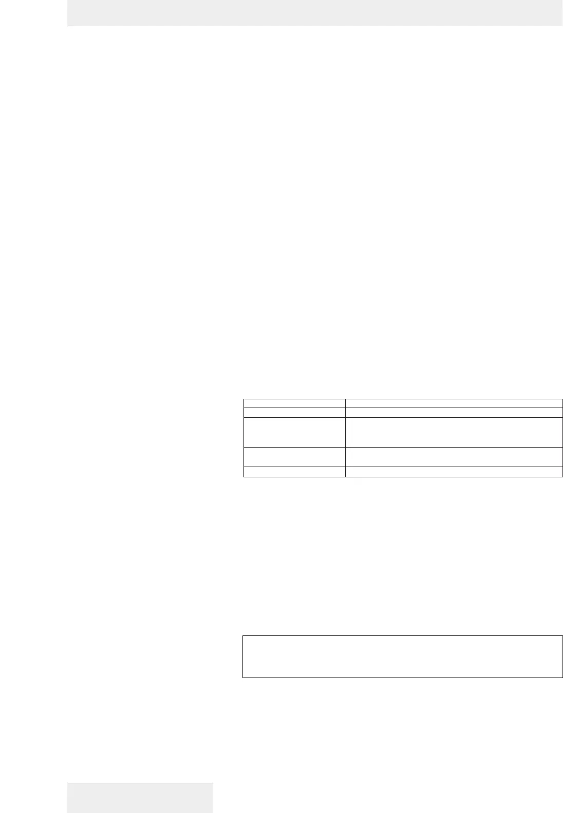
Description Rework
Servo plate face Fine stone to remove raised burrs & dings
Shear seal Fine stone to remove raised burrs & dings. Note:
grooves to supply balance pads must be present
and adequate.
Control cover Stone or lap inside face to remove raised burrs &
dings.
Spool Break sharp edges or dings.
Note: The shear seal will fit in one position only. Otherwise one side will be held up
by the lip of the servo link. Shear seal (8) must be installed to face against the cover
plate (10). This shear seal differs from shear seal (25) in that the face surface is
machined with two .094” (2.4 mm) radius scallops.