45
TM
744-862-C0-003 Rev.C
Engine Control Module (ECM)
✄
Remove page and use for quick reference
Engine Control Module Alarm Table
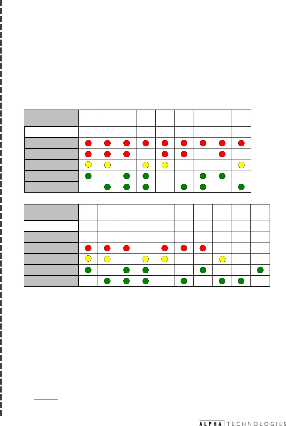
Refer to the list below for the type of alarm indicated by the LEDs.
Alarms are indicated in three ways: ECM LEDs, RS-485 communications
and alarm contact closures on ECM transponder interface. Alarm indication
on the ECM LEDs is obtained by pressing the service reset button
momentarily and noting the combination of illuminated LEDs. Pressing the
service reset switch again will reveal the next alarm in the list. When the
alarm list has been exhausted, all LEDs will flash several times and then
return to their normal functions. Placing the RAS switch in the STOP
position for three (3) seconds, then switching back to AUTO will clear
any latched alarms and start the generator if the cause of the alarm
has been corrected. The following figure shows the LED patterns and the
alarms they represent:
1. Low Oil Pressure (LO)*
2. Engine Over-Temp (OT)
3. Engine Over-Speed (OS)*
4. Engine Over-Crank (OC)*
5.
Alternator Over-Volt (OV)*
6. Gas Hazard (GH)*
7. Water Intrusion (WI)
8. Pad Shear (PS)*
9. Low Fuel Pressure (LP)***
10. Control Fail (CF)***
11. Alternator OFF (AO)
12. Self-Test Fail (TF)*
13. Low Ignition Battery (IB)
14. Auto-mode Disabled (AD)
15. Tamper (TP)
16. DC Bus fault (DC)
17. Engine Disable (ED)
18. Line Failure (LF)**
19. Service Required (SR)**
Legend: * = Latching Alarm
** = Notifications
*** = Alarm “latches” after 5 activations
Major Alarms
Abbreviation
Major
Minor
Notify
Comm
System
123456789
LO OT OS OC GH WI PS LPOV
Major Alarms
Abbreviation
Major
Minor
Notify
Comm
System
10 11 12 13 14 15 16 17 18
CF AO TF IB TP DC ED LFAD
19
SR


