20
745-738-C0-001 Rev. A
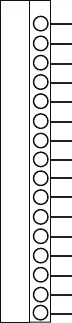
Fig. 1-20, J2, Fuel Relay PCB Connector
1.3 Alarm Operation, continued
The fi gure below shows the wiring of J2, of the Fuel Quantity Alarm PCB connector.
HALF TOTAL FUEL (NC)
BLANK
BLANK
BLANK
BLANK
BLANK
BLANK
BLANK
BLANK
BLANK
BLANK
BLANK
BLANK
BLANK
1
2
3
4
5
6
7
8
9
10
11
12
13
14
15
16
HALF TOTAL FUEL LEVEL (NO)
HALF TOTAL FUEL LEVEL RETURN
1.4 Return unit to Service
1. Restore gas pressure by opening both cylinders valves.
2. Use approved leak detection solution and test all gas fi ttings for leaks.
3. Verify all tools removed from cabinets.
4. Replace cabinet doors.
5. Restart Generator in accordance with start-up procedures in appropriate generator
document.
6. Verify normal system operation at headend.


