19745-738-C0-001 Rev. A
After completion of the installation instructions the Fuel Quantity Alarm will be operational. Verify
green LED is on and blinking. This is the PCB “heartbeat” indicating the PCB is operating.
The RED LED is an alarm LED. The red LED will be lit when the Fuel quantity is less than ½ of total
fuel in any combination (i.e., if LP1 is full and LP2 is empty, or if both tanks are half empty).
1.3 Alarm Operation
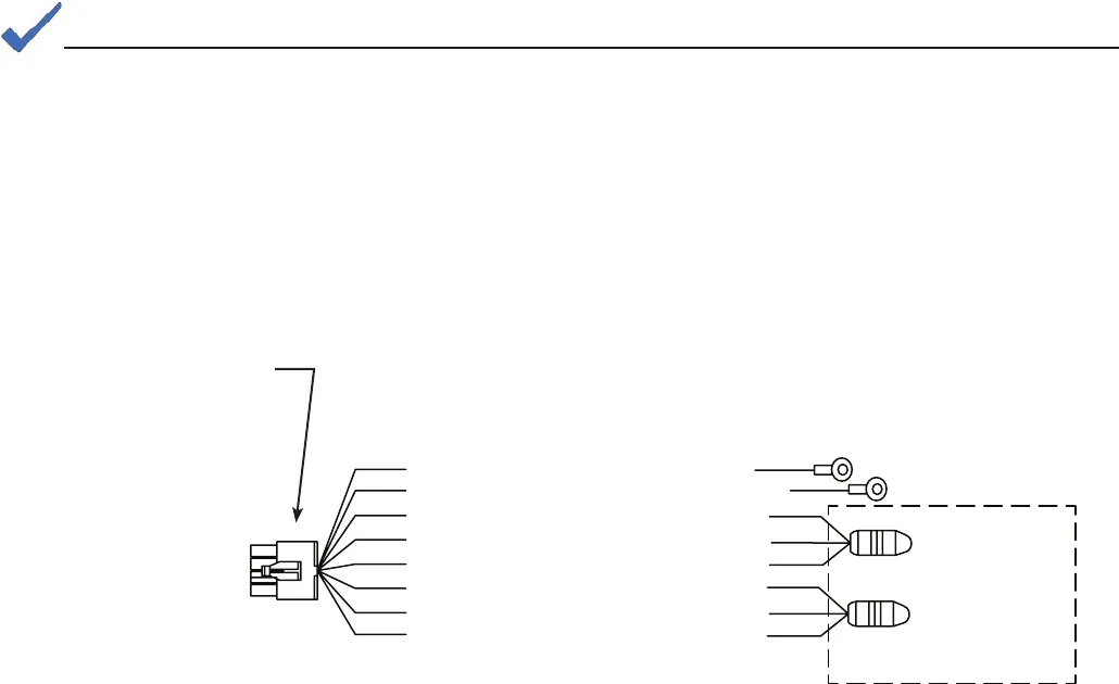
Fig. 1-19, Fuel Quantity Alarm Wiring Harness
PIN 8 IGN BATT NEGATIVE
PIN 7 IGN BATT POSITIVE
PIN 6 LP2 SENSOR GROUND
PIN 5 LP2 SENSOR 5V SUPPLY
PIN 4 LP2 SENSOR OUTPUT
PIN 3 LP1 SENSOR GROUND
PIN 2 LP1 SENSOR 5V SUPPLY
PIN 1 LP1 SENSOR OUTPUT
LP2 SENSOR
LP1 SENSOR
CE3G COMPARTMENT
To J1,
Fuel Relay
PCB
The fi gure below shows the wiring between J1 of the Fuel Quantity Alarm PCB, the ignition battery
and the fuel gauge dials on the LPG tanks in the CE-G compartment.
NOTE
If both modules are not installed on the cylinders there will be no alarm. If one MODULE is disconnected and
one is still connected there will be an alarm.


