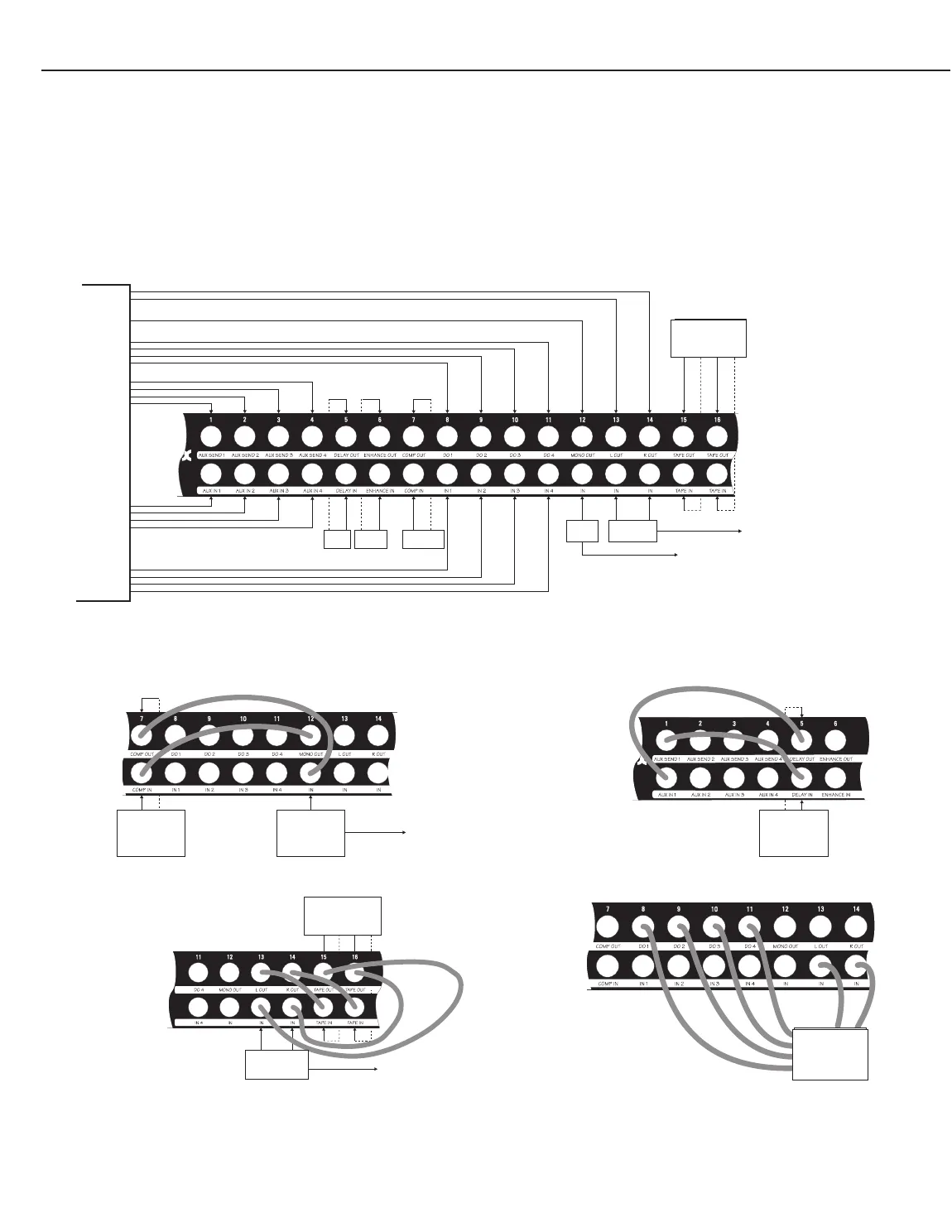
EXAMPLES OF PATCHBAY SETUPS
Figure 3: Possible Initial Patchbay Setup
(Examples of patchpoints for this setup are shown below)
(3-A) Patching A Compressor To A Monitor (Mono) Mix (3-B) Patching An Effects Device To A Mixer Aux Channel
(3-C) Patching a Tape Recorder To The Main Outs (3-D)Patching a Multitrack Tape Recorder Into The System
In this example, the PB-48 supports:
1 4-channel mixer: 4 inputs
4 direct outs
4 aux sends and returns
1 monitor (mono) output
L/R stereo outputs
2 effects devices (e.g., delay, enhancer)
1 signal processor (e.g., compressor)
1 2-track cassette deck
1 4-track recorder (in Figure 3-D)
2. ALL CONNECTIONS TO REAR OF PATCH BAY
It is common to set up your patchbay with some boards normalled and
others de-normalled, so that your front panel patchpoints are as flexible
as required and you maximize patchbay real estate as much as possible.
For example, to compress a mixer’s mono out signal, consider the follow-
ing (as shown in Figure 3): keep one circuit board normalled, as shipped
(e.g., #12), and connect the mixer’s mono output to its rear upper jack,
then connect the power amp input to its rear lower jack; de-normalize a
different circuit board (e.g., #7) and add a compressor to this board by
connecting the compressor input to its rear lower jack and the compres-
sor output to its rear upper jack. To compress the mono output via the
PB-48’s front panel patchpoints (Figure 3-A), connect the mono output to
the compressor input with a patch cable from the normalled front upper
jack to the de-normalled front lower jack, then connect the compressor
output to the power amp with a patch cable from the de-normalled front
upper jack to the normalled front lower jack. Other examples are shown
in Figures 3-B through 3-D. It should be noted that since this patch bay is
TRS, other applications may include using stereo unbalanced signals
(tip-left, ring-right, sleeve-ground) or unbalanced insert signals (tip-return,
ring-send, sleeve-ground for example) on a single “2-conductor plus
shield” cable.
3
2. ALL CONNECTIONS SHOWN ARE TO REAR OF PATCH BAY
Tape
Recorder
Out In Out In
L L R R
Tape
Recorder
Out In Out In
L L R R
OUT OUT
IN
IN 4-TRACK
IN RECORDER
IN