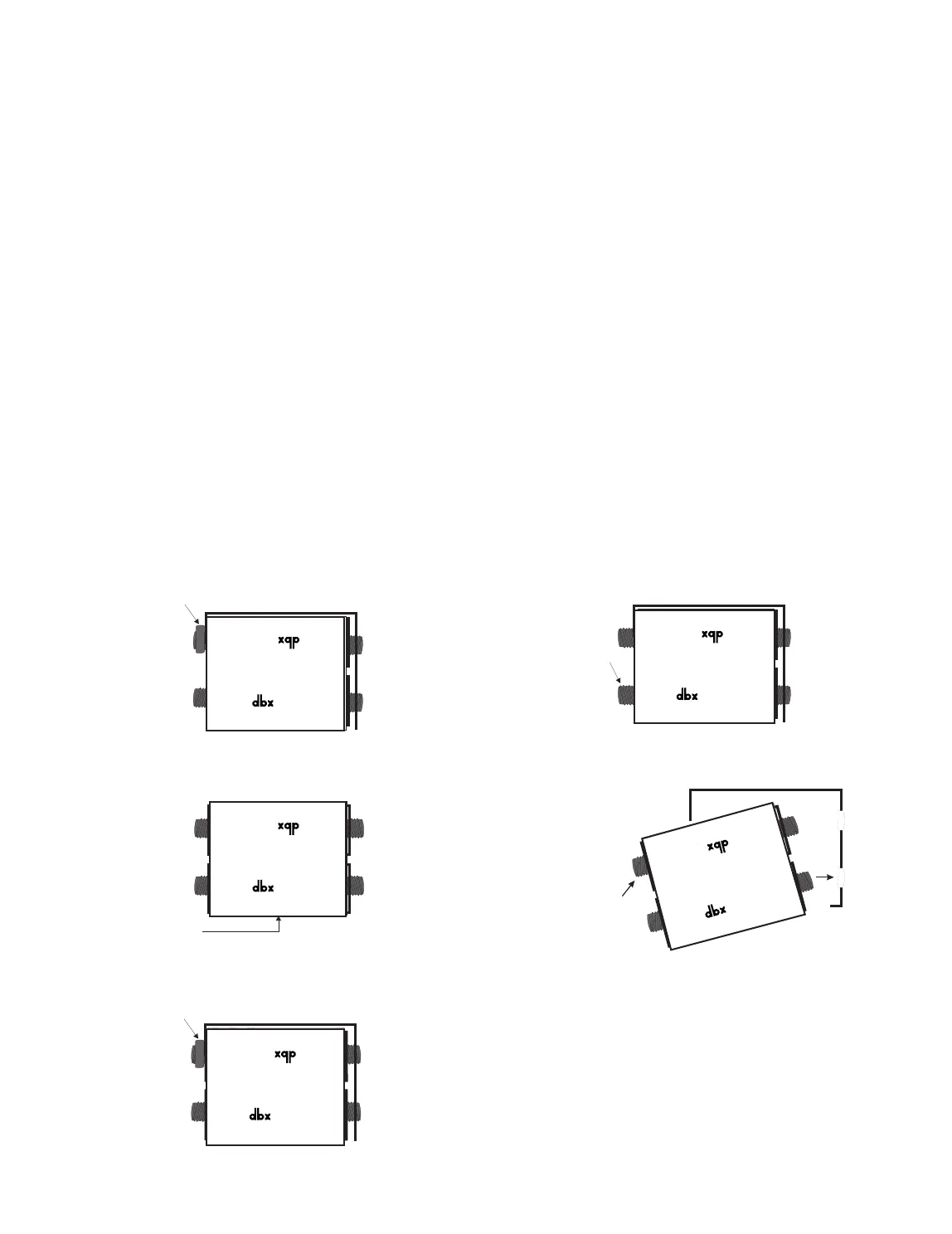
The front-panel upper jacks in a half-normalled/normalled patchbay are
usually considered to be outputs because each front-panel upper jack is
wired directly to its corresponding rear-panel upper jack, where the audio
source is connected (see Figure 1-B). For example, in the half-normalled
situation, connecting from a front-panel upper jack output to the input of a
headphone amp allows you to “listen in” to the signal from the corre-
sponding rear jack. This setup is sometimes called a Mult-ed patch,
because the patchbay simultaneously routes the rear-panel signal (i.e.,
signal fed to the rear upper jack) to multiple points: one output to the
rear-panel lower jack and one output at the front-panel upper jack. A pos-
sible setup might have a mono mix sent to the rear upper jack, the routed
signal at the lower rear jack fed to the power amp, and the routed signal
at the front-panel upper jack connected to a tape recorder input for a
mono tape mix.
The front-panel lower jacks in a half-normalled/normalled patchbay are
called inputs because each front-panel lower jack is wired directly to its
corresponding rear-panel lower jack which is connected to an equipment
input. Plugging into a front-panel lower jack interrupts the signal fed from
the corresponding rear-panel upper jack and provides a new input source
to the rear-panel lower jack (see Figure 1-C). For example, inserting a
DAT recorder signal into the front-panel lower jack routes the tape signal
directly to the corresponding rear-panel lower jack. Note, however, that
the front-panel upper jack retains the signal from the rear-panel upper
jack.
The front-panel lower jack input can also be used to alter its correspond-
ing rear-panel upper jack signal when the board assembly is correctly
patched to a signal processor (e.g., an equalizer, compressor, gate, etc.).
Start with a mixer and amp connected to one vertical pair of the patch-
bay’s rear-panel jacks, as described before. Then, connect the front-
panel upper patchbay jack (which has the mixer’s output signal) to the
processor’s input, and connect the processor’s output to the front-panel
lower jack input which feeds the amp.
To connect devices like effects or signal processors directly to the PB-
48’s rear panel jacks, so that they are accessible through a vertical pair
of front panel patchpoints, the PB-48 must be De-Normalized (see Figure
1-D for example and Figure 2 for customization instructions).
In a De-Normalled (or Non-Normalled) patchbay, each front panel jack
is routed directly and only to the corresponding rear-panel jack (i.e., first
upper front to first upper rear, first lower front to first lower rear, etc.). The
purpose for de-normalled patch points is convenience so that equipment
rear-panel jacks are easily accessible. De-normalled operation is useful
with effects devices or other input/output devices for which there is no
“normal” connection between it and other equipment. For example, a
compressor’s inputs and outputs may be patched into the insert point of
any mixer channel or may be used on the master outputs at mixdown
and, therefore, has no “normal” connection. Also, for consistency, the
usual patch bay setup connects outputs to rear-panel upper jacks and
inputs to rear-panel lower jacks, so normalling this vertical pair would
cause an effects device’s output to be connected directly back to its
input. This unintentional normalling is not only useless, but feedback from
output to input can cause the equipment to oscillate and emit a nasty
shriek.
Although a De-Normalled circuit board eliminates the opportunity to
“mult” outputs, the number of possible “straight” signal connections is
increased. For example, to provide access to all the inputs of a 16-chan-
nel mixer, connect the first eight pairs of the patchbay’s rear-panel jacks
respectively to the 16 mixer inputs. Now, plugging a synthesizer into one
of the front-panel patchpoints routes the synthesizer signal directly to the
corresponding mixer input. Note that all of this can be accomplished
using only 1/3 of the patchbay. The drawback, of course, is that any con-
nection to a de-normalled patch point must be made with a patch cable.
2